
Method for changing the clutch torque in a clutch in the power train of a vehicle having an automated manual shift transmission

a technology of automatic manual shift transmission and clutch, which is applied in the direction of clutches, control devices, driver input parameters, etc., can solve the problem of not being able to detect the engine speed drop, and achieve the effect of improving the effect of establishing the clutch biting poin

Inactive Publication Date: 2006-06-15
SCHAEFFLER TECH AG & CO KG
View PDF13 Cites 2 Cited by
  • Summary
  • Abstract
  • Description
  • Claims
  • Application Information

AI Technical Summary

Benefits of technology

The present invention provides a method for changing the clutch torque in a vehicle with an automated manual shift transmission in a creep drive mode. The method is based on the monitoring of operating parameters of the vehicle, such as the strength of the actuation of the brakes or the engine torque, and the clutch torque is adjusted accordingly. This allows for a more comfortable creep drive mode without causing the engine to die or the clutch to slip. The method can be used in both vehicles with and without a creep drive mode. Additionally, the method can be used in power trains where the clutch is positioned between the engine and the transmission input. Overall, the method improves the performance and comfort of the vehicle's power train in the creep drive mode.

Problems solved by technology

However, if a diesel engine is used as the drive motor, it reacts significantly more rapidly than a gasoline engine to a reduction in the engine speed, through an increase in the engine torque output because of the combustion, so that a noticeable drop in the engine speed may not be perceived, but rather the driver of the vehicle would perceive a push of the engine against his braking intent.

Method used


Image

  • Method for changing the clutch torque in a clutch in the power train of a vehicle having an automated manual shift transmission
  • Method for changing the clutch torque in a clutch in the power train of a vehicle having an automated manual shift transmission
  • Method for changing the clutch torque in a clutch in the power train of a vehicle having an automated manual shift transmission

Examples


Embodiment Construction

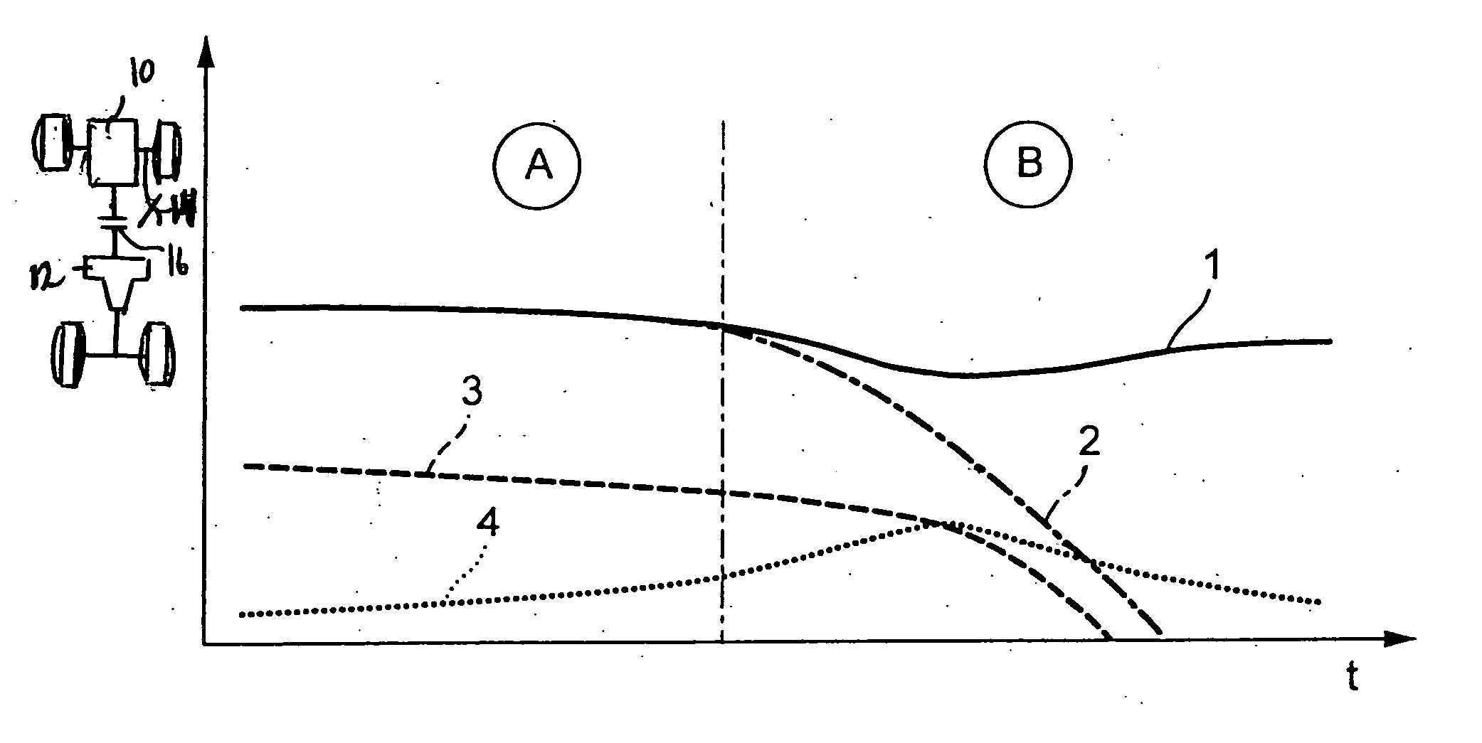
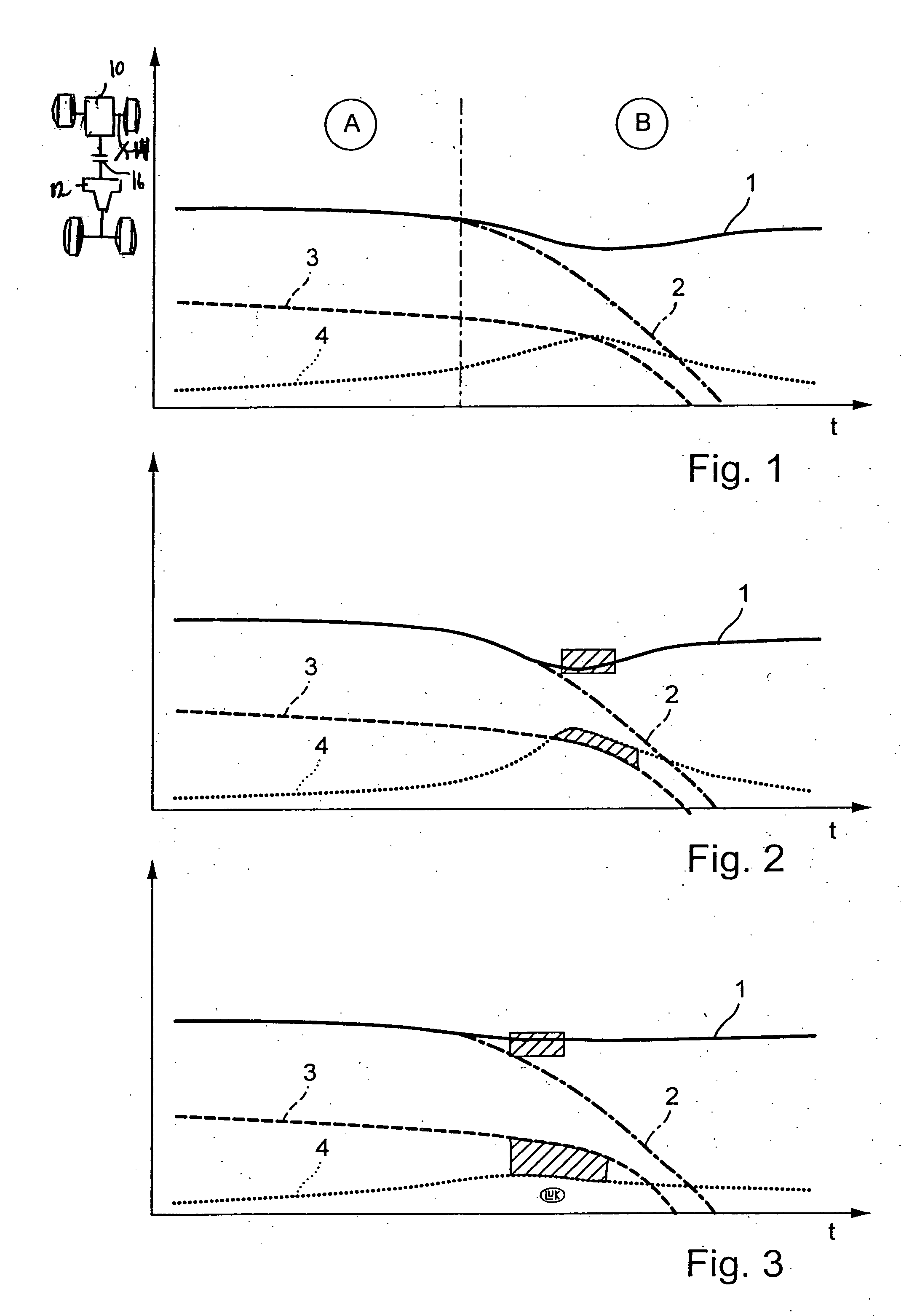
[0031]FIG. 1 of the drawing shows a schematic illustration of the change in the clutch torque as a function of the strength of the actuation of the brake by the driver of the vehicle.

[0032] This is a qualitative illustration, using which the method according to the present invention is to be explained. The region identified with A shows curves when the driver of the vehicle brakes only lightly, while the region identified with B shows curves in the event of strong braking.

[0033] In region A, engine speed 1 and transmission input shaft speed 2 run largely uniformly and fall slightly due to the light braking action. Clutch torque 3 also falls slightly, while engine torque 4 increases slightly. The clutch is closed and operates essentially without slip. This may be the situation when parking.

[0034] If the driver now actuates the brake more strongly, it is provided according to the present invention that clutch torque 3 is reduced with a higher gradient than is the case in the event ...


PUM


Abstract

A method for altering the coupling torque of a coupling in the drive train of a vehicle with an automatic gearbox and / or automatic coupling in a creep drive mode of a vehicle. According to the invention, the coupling torque is altered according to at least one variable, the parameter of the vehicle describing the creep drive mode thereof.

Description

CROSS-REFERENCE TO RELATED APPLICATIONS [0001] This is a divisional of U.S. patent Ser. No. 10 / 739,703, a continuation of International Application No. PCT / DE02 / 02304, filed Jun. 24, 2002, and claims priority to German Patent Application No. 101 30 874.4, filed Jun. 27, 2001, which are hereby being incorporated by reference herein.BACKGROUND INFORMATION [0002] The present invention relates to a method for changing the clutch torque of a clutch in the power train of a vehicle having an automated manual shift transmission and / or an automated clutch in a creep drive mode of the vehicle. The present invention also relates to a method for changing the clutch torque of a clutch in the power train of a vehicle having an automated manual shift transmission and / or an automated clutch to establish the biting point of the clutch. [0003] When a vehicle having an automated manual shift transmission and / or an automated clutch is moved in a creep drive mode to park in a parking space, for example,...

Claims


Application Information

Patent Timeline
Patent Type & Authority Applications(United States)
IPC IPC(8): B60W10/02F16D48/06F16D48/02
CPCB60W2540/12Y10T477/6392F16D2500/30406F16D2500/3065F16D2500/3068F16D2500/3144F16D2500/50206F16D2500/50257F16D2500/5048Y10T477/755Y10T477/78Y10T477/79Y10T477/753Y10T477/743Y10T477/757F16D48/06B60W30/18063
Inventor RIEGER, CHRISTIANGERHART, JUERGENJUNG, MARIOVORNEHM, MARTIN
Owner SCHAEFFLER TECH AG & CO KG
Learn More