
Gear change control device and method

Active Publication Date: 2006-06-15
YAMAHA MOTOR CO LTD
View PDF5 Cites 38 Cited by
  • Summary
  • Abstract
  • Description
  • Claims
  • Application Information

AI Technical Summary

Benefits of technology

[0007] Therefore, one object of the present invention is to provide a gear change control device and method that can more smoothly change transmission gears when the vehicle starts to run.

Problems solved by technology

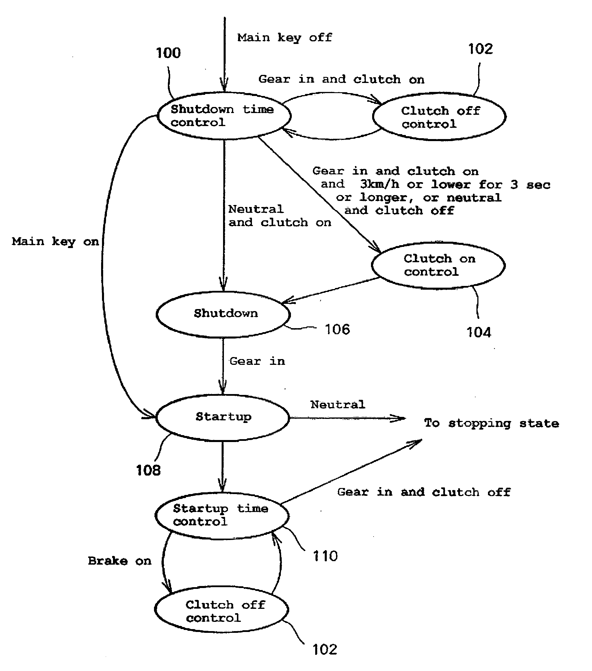
However, it is difficult to apply the same gear change control routine when the vehicle starts to run.
That is, when the vehicle starts to run, the vehicle speed is not increased enough and the rotational speed difference between the driving member (e.g., a friction disk for a wet multi-plate clutch) and the driven member (e.g., a clutch disk for a wet multi-plate clutch) of the clutch is often larger than during running conditions.
Therefore, the gear change control routine that is used while the vehicle is running will not provide smooth gear changes when the vehicle starts to run.
This may impair the riding comfort of the straddle-type vehicle.

Method used


Image

  • Gear change control device and method
  • Gear change control device and method
  • Gear change control device and method

Examples


Embodiment Construction

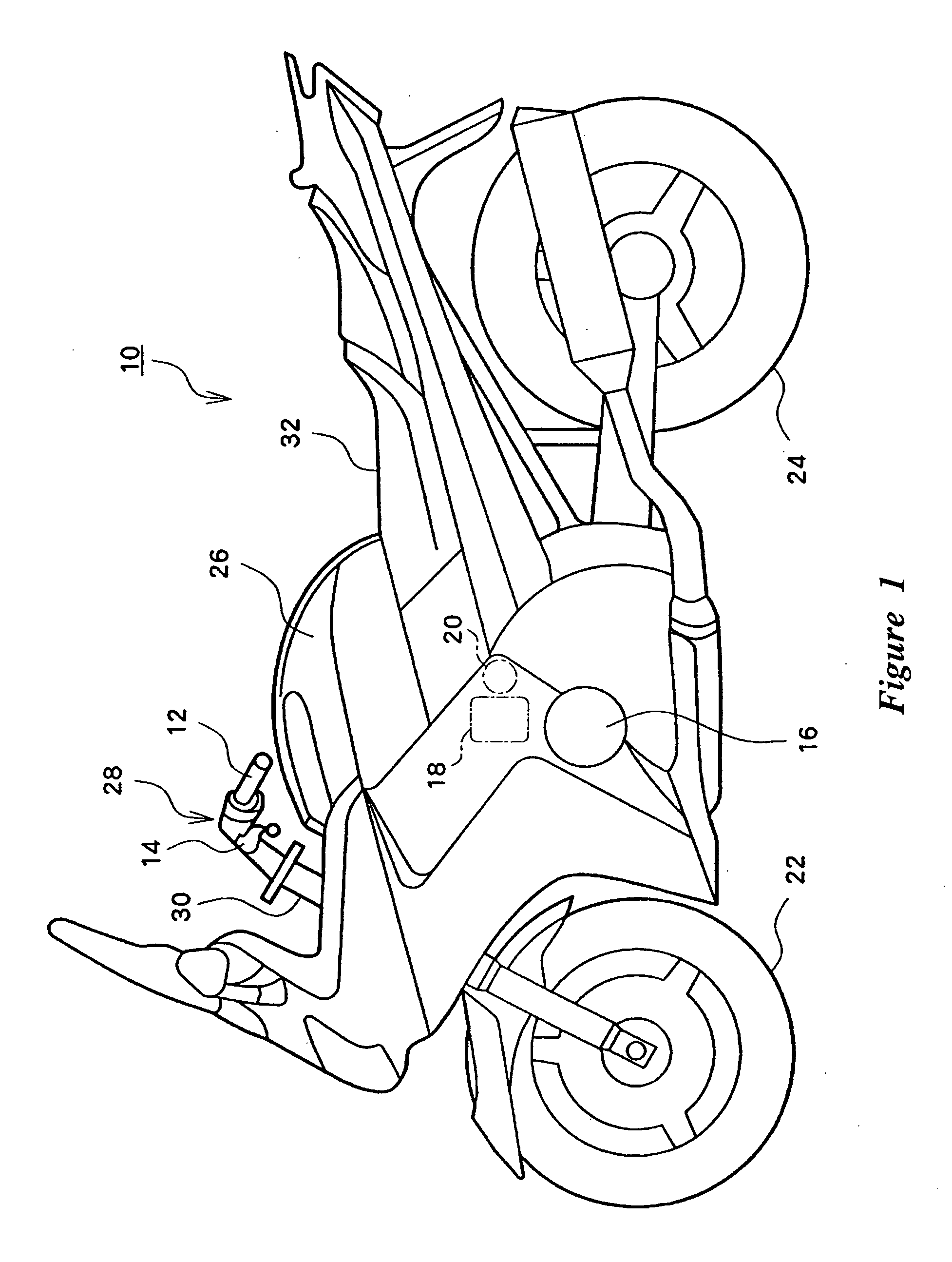
[0025]FIG. 1 is an external side view of a motorcycle according to an embodiment of the present invention. In illustrated embodiment, the motorcycle 10 can include a front wheel 22 and a rear wheel 24. Handlebars 28, which can extend transversely with respect to the running direction of the vehicle 10, can be attached to a top or upper end of a front fork 30. The bottom or lower end of the front fork 30 can be, in turn, attached or coupled to the front wheel 22. A grip 12 and a clutch lever 14 can be attached or coupled to a first (e.g., left) end of the handlebars 28 and an accelerator grip and a brake lever (not shown) can be attached to the other (e.g., right) end of the handlebars 28.

[0026] With continued reference to FIG. 1, the motorcycle 10 can be provided with a seat 32 that is positioned on an upper part of the motorcycle 10. The seat 32 can be configured such that a rider can straddle the motorcycle 10. Thus, the motorcycle 10 of FIG. 1 is a straddle-type, street vehicle,...


PUM


Abstract

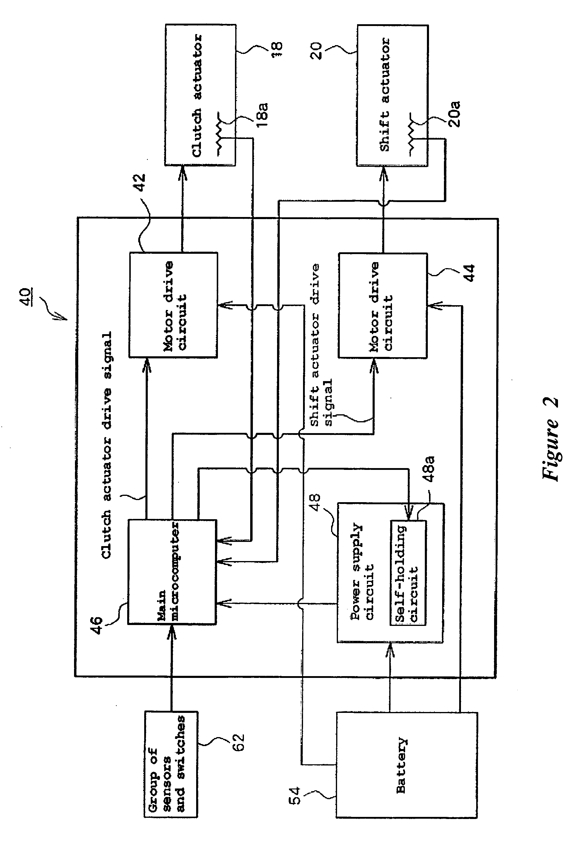
A gear change control device is provided for a straddle-type vehicle having a clutch and a transmission. The device includes a clutch actuator configured to engage and disengage the clutch. A transmission actuator is configured to change a gear of the transmission. At least one sensor is configured to sense an operational condition of the straddle type vehicle. At least one switch is configured to generate a gear change command. A controller is operatively connected to the clutch actuator, the transmission actuator, the at least one sensor, and the at least one switch. The controller is configured to change gears in response to the gear change command and during the gear change reengage the clutch under either a first control routine or second, different control routine based upon the operational condition of the straddle-type vehicle determined by the at least one sensor.

Description

CROSS-REFERENCE TO RELATED APPLICATIONS [0001] This application claims priority under 35 U.S.C. § 119 to Japanese Patent Application No. 2004-359229, filed on Dec. 10, 2004, the entire content of which is expressly incorporated by reference herein. BACKGROUND OF THE INVENTION [0002] 1. Field of the Invention [0003] This invention relates to a device and method for controlling gear changes, and more particularly, to a device and method for controlling gear changes in a straddle-type vehicle. [0004] 2. Description of the Related Art [0005] Japanese patent publication JP-A-Hei 10-287150 describes a straddle-type vehicle (e.g., a motorcycle) that has a clutch and a transmission driven by actuators (e.g., motors). Vehicles with such gear change control systems are increasingly popular. When a rider of such a straddle-type vehicle inputs a gear change command manually, the clutch and the transmission in conjunction with each other automatically perform a series of gear change operations. ...

Claims


Application Information

Patent Timeline
IPC IPC(8): B60W10/04B60W10/02B60W10/10F16D28/00F16D48/02F16D48/06F16H63/46
CPCF16D48/064Y10T477/641F16D2500/10412F16D2500/1045F16D2500/30415F16D2500/30426F16D2500/3069F16D2500/30806F16D2500/3108F16D2500/31426F16D2500/3144F16D2500/50224F16D2500/70412F16D2500/70663Y10T477/6403Y10T477/6414Y10T477/688Y10T477/75F16D2500/1023
Inventor ZENNO, TORU
Owner YAMAHA MOTOR CO LTD
Learn More