
Current threshold circuit

Active Publication Date: 2006-06-15
NXP USA INC
View PDF11 Cites 5 Cited by
  • Summary
  • Abstract
  • Description
  • Claims
  • Application Information

AI Technical Summary

Benefits of technology

[0010] The current threshold circuit of the present invention substantially meets these needs and others. In one embodiment, a current threshold circuit includes a series impedance, a reference voltage source, and a comparison module. The series impedance couples an output of a current source to a load, wherein impedance of the series impedance is substantially less than impedance of the load. The referen

Problems solved by technology

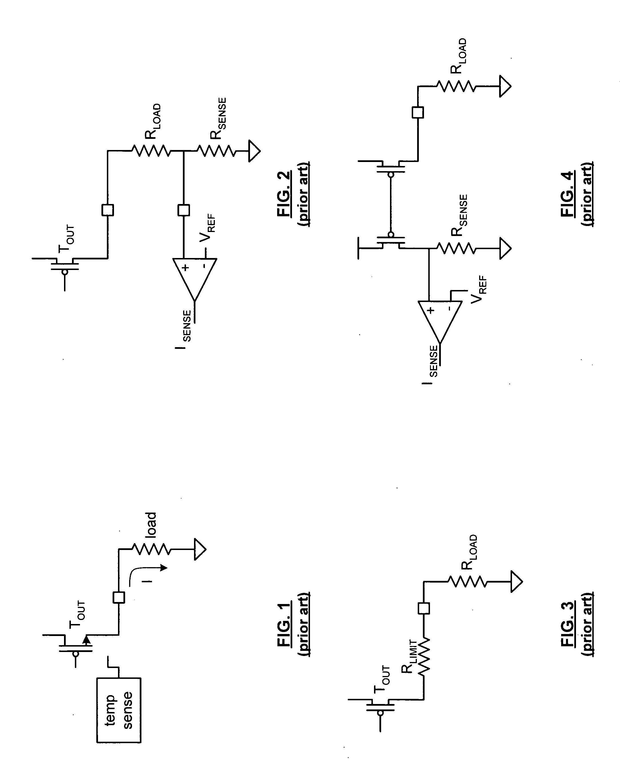
While such a circuit provides overload protection, it does so at the cost of a temperature sensing circuit, which may not respond fast enough to avoid overloading the power rails.
While this provides overload protection, it does at the cost an additional sense pin for each output.
Further, the sense resistor adds impedance to the output, which lowers the overall effeciency of the output due to its power consumption and reduces the voltage swing of the output.
An issue with this embodiment is the loss of voltage output swing for the resistive load as well as the inefficiency due to power consumption of the limiting resistor.
An issue with this embodiment of a current limiting circuit is that when the output voltage swings from rail-to-rail, the drain source voltage of the output transistor has a wide variation, which causes the mirroring transistor to produce an inaccurate mirroring current.
Such inaccurate current mirroring cause unacceptable variations in the current limiting function.

Method used


Image

  • Current threshold circuit
  • Current threshold circuit
  • Current threshold circuit

Examples


Embodiment Construction

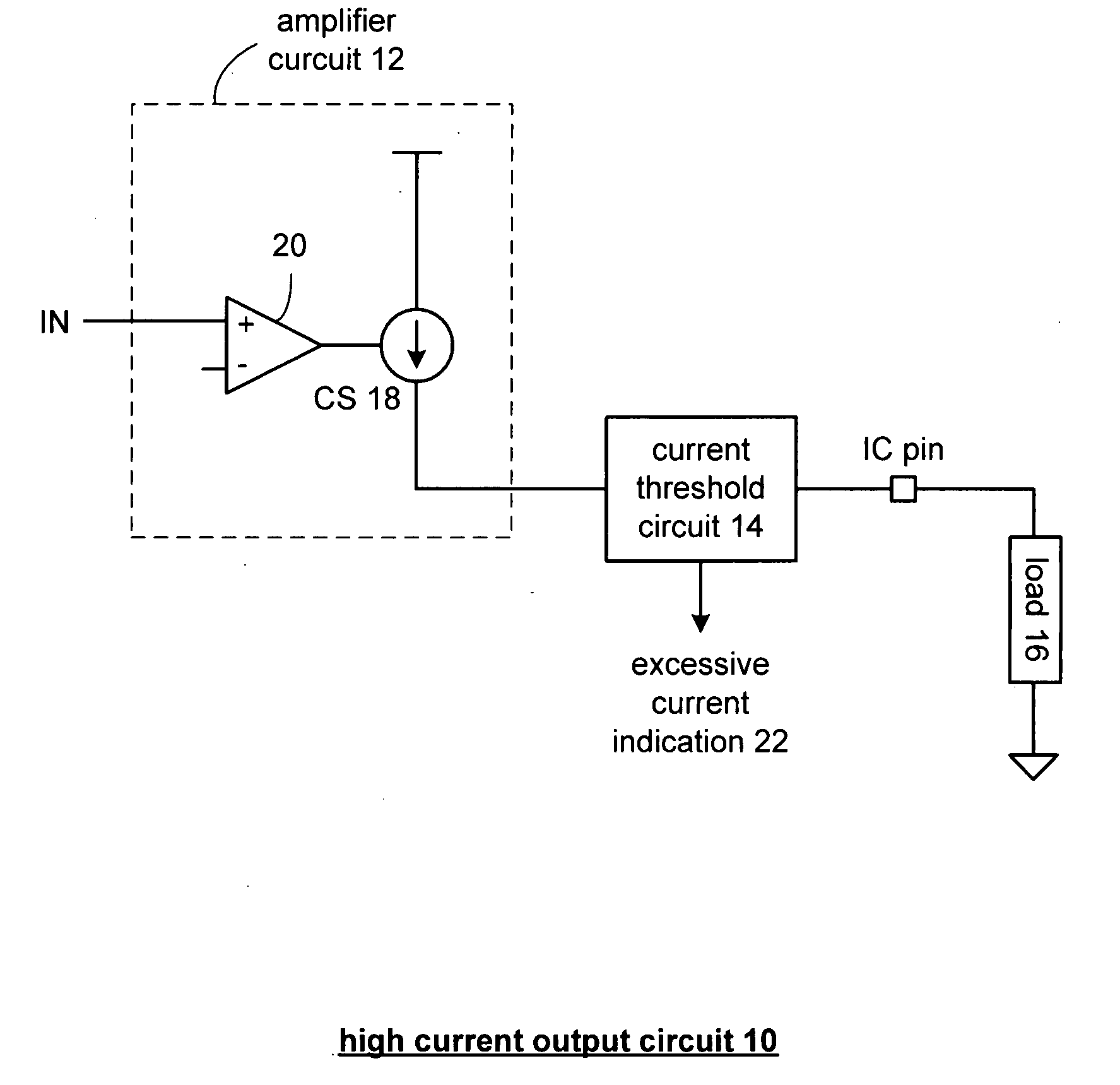
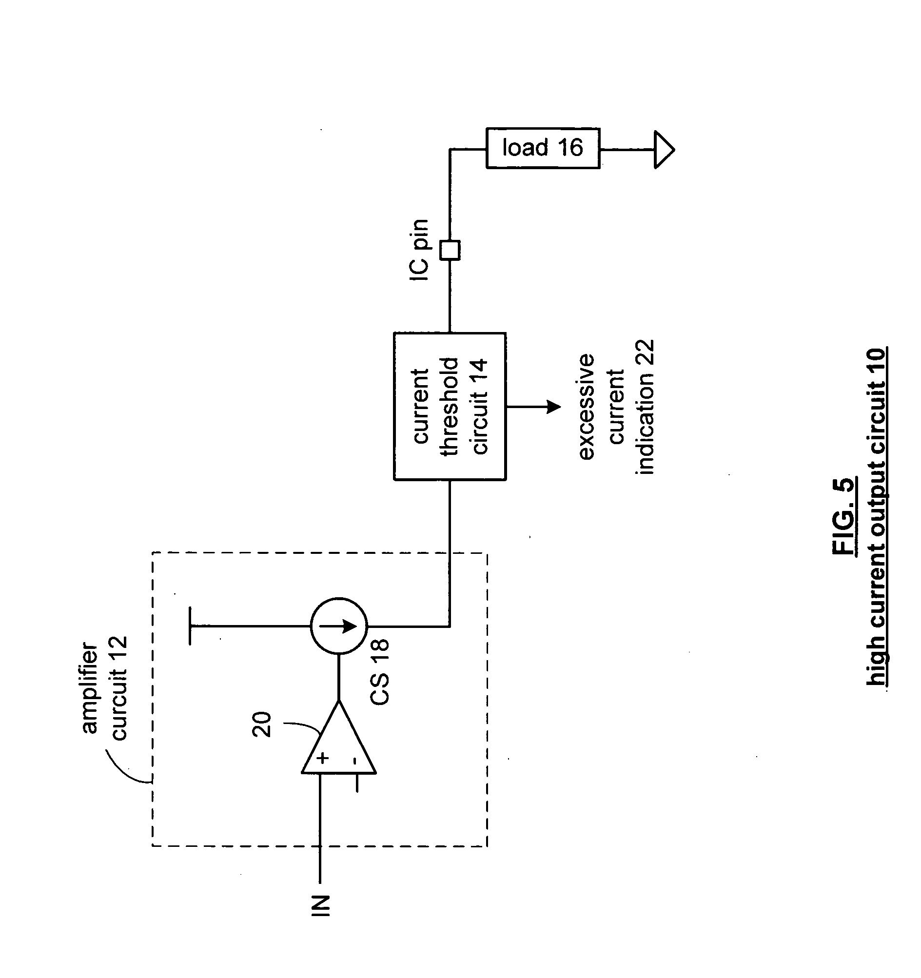
[0020]FIG. 5 is a schematic block diagram of a high current output circuit 10 that includes an amplifier circuit 12, a current threshold circuit 14, an integrated circuit (IC) pin and a load 16. The amplifier circuit 12 and the current threshold circuit 14 are implemented on an integrated circuit while the load is typically off-chip. The amplifier circuit 12 may be an amplifier and / or a line driver. The load may be a speaker, headphone, et cetera.

[0021] The amplifier circuit 12 includes an amplifier 20 and a current source 18. The output of the amplifier 20 regulates the current produced by current source 18. In one embodiment, the amplifier 20 may be connected as an amplifier where the positive input is coupled to receive an input signal and the negative input is coupled to a reference voltage or other reference source. Alternatively, the amplifier circuit 12 may be used as a line driver where the positive input of the amplifier receives the input signal and the negative input of ...


PUM


Abstract

A current threshold circuit includes a series impedance, a reference voltage source, and a comparison module. The series impedance couples an output of a current source to a load, wherein impedance of the series impedance is substantially less than impedance of the load. The reference voltage source is operably coupled to produce a reference voltage differential. The comparison module is operably coupled to compare the reference voltage differential with a differential voltage of the series impedance, wherein the comparison module generates an excessive current indication when the differential voltage of the series impedance compares unfavorably to the reference voltage differential.

Description

BACKGROUND OF THE INVENTION [0001] 1. Technical Field of the Invention [0002] This invention relates generally to integrated circuits and more particularly to excessive output current detection of such integrated circuits. [0003] 2. Description of Related Art [0004] Integrated circuits (IC) are known to be used in a multitude of electronic devices and are required to provide sufficient output power to driver components coupled to the IC. For example, an audio processing IC (e.g., audio codec, MP3 player, etc.) has at least one output to drive headphones. To protect an IC from an overload and / or short circuit on such a high powered output, the IC includes a current limiting circuit. [0005]FIG. 1 is an embodiment of a known output current limit circuit that includes an output drive transistor (Tout) and a temperature sensing circuit that is in the vicinity of the transistor. The output drive transistor provides an output current to a load via an IC pin. If the output current becomes e...

Claims


Application Information

Patent Timeline
IPC IPC(8): H02H7/20
CPCG05F1/573
Inventor FELDER, MATTHEW D.MAY, MARCUS W.
Owner NXP USA INC
Learn More