
Fueling nozzle with integral molecular leak sensor

a technology of molecular leak detection and fueling nozzle, which is applied in the field of chemical detection, can solve the problems of not being able to use the fueling nozzle in the first place, unable to ignite leaking hydrogen, and the thermal conductivity sensor may pose an “ignition source”

Inactive Publication Date: 2006-06-15
AIR PROD & CHEM INC
View PDF11 Cites 8 Cited by
  • Summary
  • Abstract
  • Description
  • Claims
  • Application Information

AI Technical Summary

Benefits of technology

Enables accurate hydrogen level monitoring and automatic control during transfer, preventing unsafe conditions and maintaining sensor functionality across a wide range of concentrations and environments, thereby ensuring safe and efficient hydrogen transfer.

Problems solved by technology

For example, thermal conductivity sensors may pose an “ignition source” problem that can ignite leaking hydrogen, when the hydrogen concentration is greater than about 4% per volume; electrochemical and MOS technologies require the presence of oxygen to operate; optical sensors cannot get wet or be exposed to a wet environment and therefore must typically be used in a clean and dry environment.
However, as mentioned earlier, this approach cannot be used within the fueling nozzle because of its mode of operation, because its hot wire-filament, can cause an unsafe condition, by generating a spark source.
This is also not acceptable because mixing air, or oxygen, with hydrogen (i.e., 4%-74% hydrogen in air or 4%-90% hydrogen in oxygen) in the presence of an ignition source (e.g., at least 0.02 millijoules), results in a dangerous condition.
The most ardent problems of MOS-based sensor manufacturing are the reproduction of resistive properties and possibility of the formation of thin film metal oxide sensitive layers in certain configurations.

Method used


Image

  • Fueling nozzle with integral molecular leak sensor
  • Fueling nozzle with integral molecular leak sensor
  • Fueling nozzle with integral molecular leak sensor

Examples


Embodiment Construction

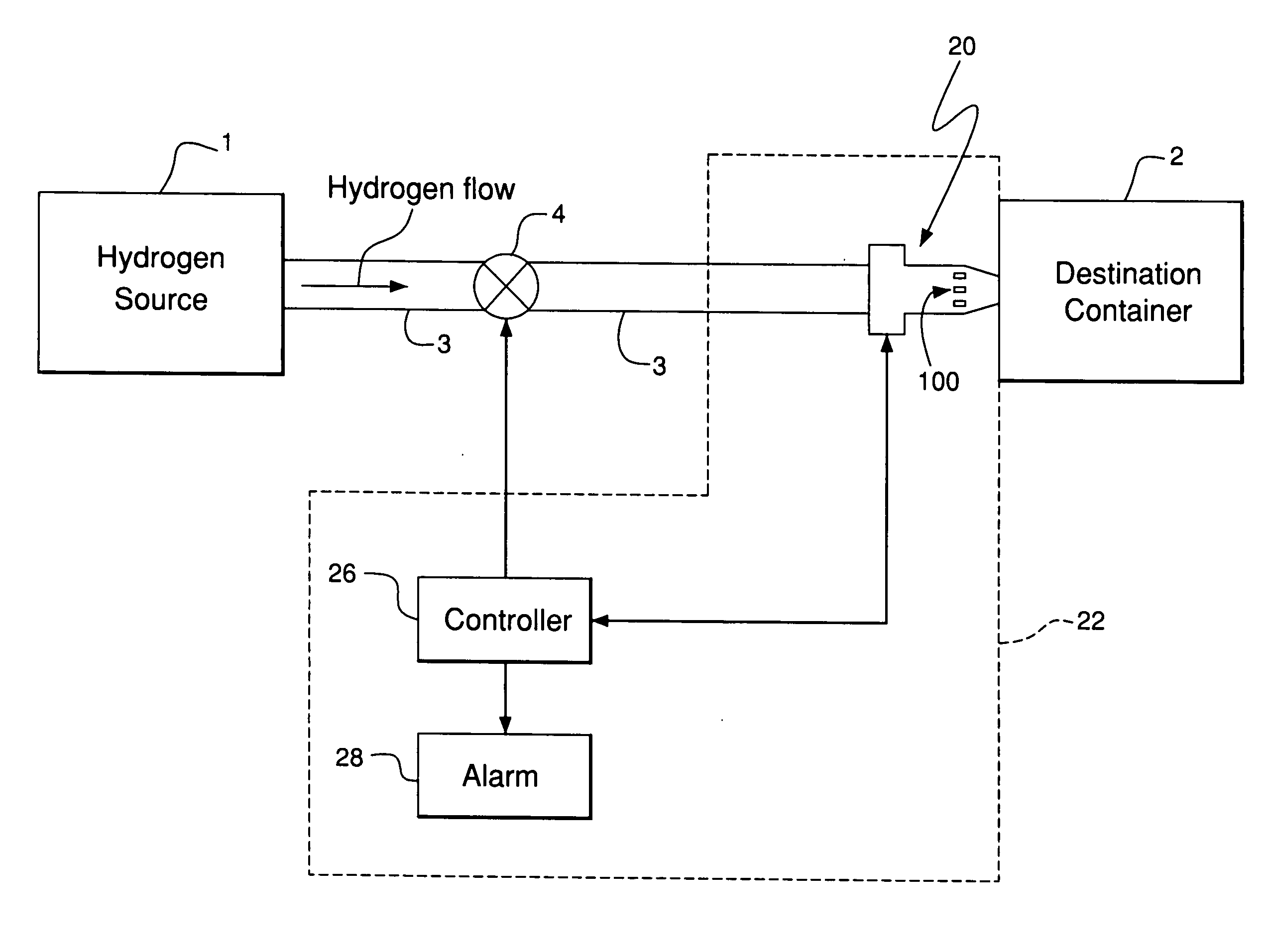
[0027] The present invention provides an apparatus and method for accurately measuring the hydrogen concentration within a hydrogen fueling nozzle during transfer of hydrogen from one storage container to another storage container and automatically alerting and / or safely controlling such transfer as required.

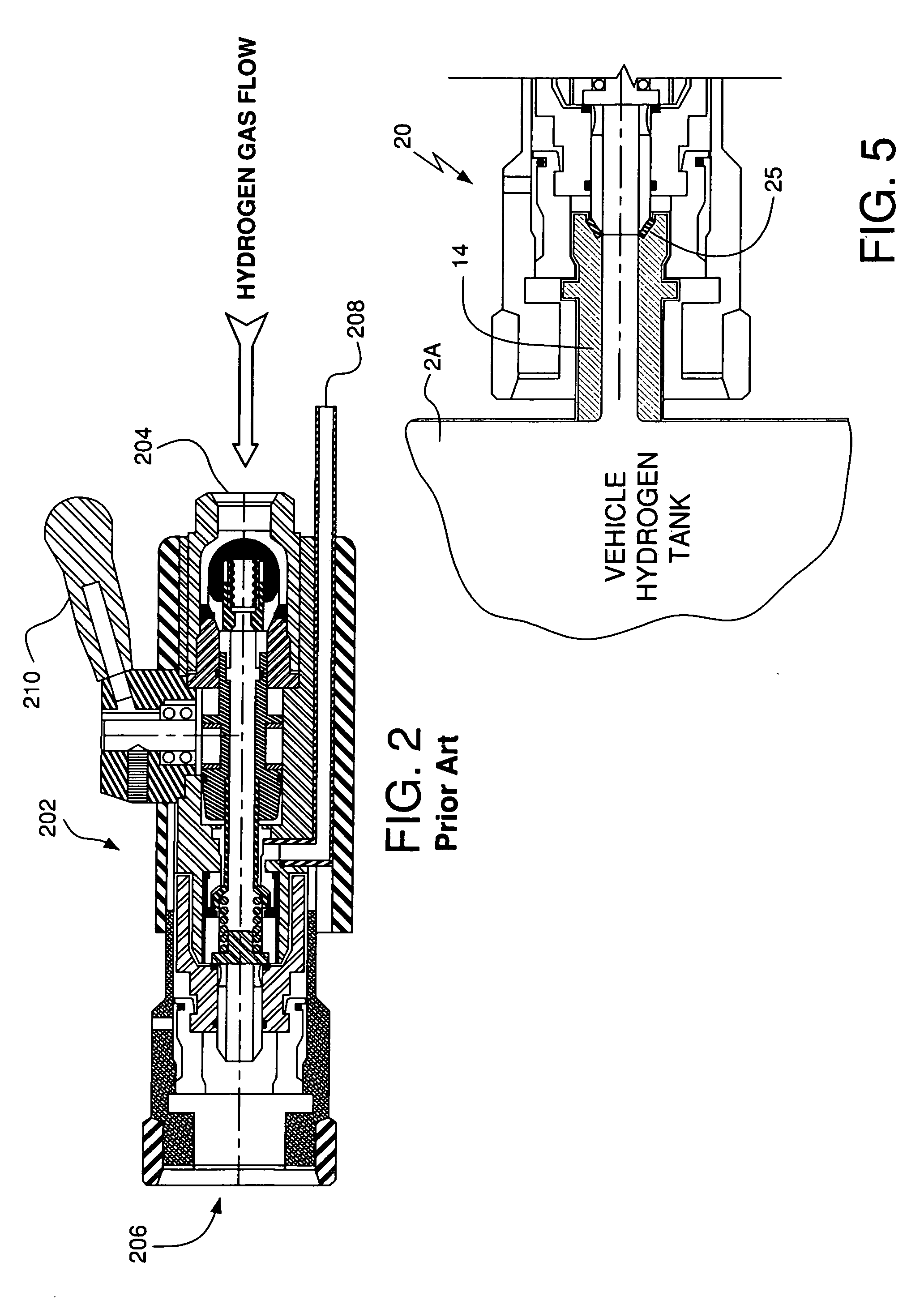
[0028] As shown in FIG. 1, hydrogen is transferred from a first container 1 to a second or “destination” container 2 via a transfer line 3 and the fueling nozzle 20. The first container 1 may comprise any supply source such as a pressure vessel (wherein a pressure vessel is defined as a closed container capable of withstanding internal pressure greater than ambient pressure, and in as used in this Specification, typically less than 900 atmospheres), or hydrogen generator such as a hydrolysis unit or a reformer, a gas compressor, or a liquid hydrogen pump. The second container 2 may comprise a pressure vessel.

[0029] Furthermore, this fueling nozzle 20 forms part of a monitoring...


PUM

PropertyMeasurementUnit
temperatureaaaaaaaaaa
pressureaaaaaaaaaa
temperatureaaaaaaaaaa

Abstract

An apparatus and process for measuring the concentration of hydrogen gas being transferred through a nozzle from a source container to a destination container and for providing an alert and / or taking action where hydrogen gas leaks may create an unsafe condition. The invention can accurately and reproducibly respond to and measure the absolute hydrogen gas concentration within the nozzle housing using hydrogen gas sensors that are selective only to hydrogen, which do not require the presence of oxygen to operate and which do not saturate when hydrogen safety levels are reached. These sensors are positioned inside the nozzle housing to allow for the direct and immediate knowledge of the presence of hydrogen gas that cannot be safely determined by other means. An apparatus and process for detecting leaks of liquid hydrogen through a nozzle during transfer of liquid hydrogen from a source container to a destination container are also discussed.

Description

CROSS REFERENCE TO RELATED APPLICATIONS [0001] This is a divisional of application Ser. No. 10 / 452,549, filed on May 30, 2003, the specification and claims which are incorporated by reference and made a part of this application.BACKGROUND OF THE INVENTION [0002] The present invention relates generally to chemical detection and more particularly to an apparatus and process for the measurement of hydrogen, a flammable material, when the hydrogen is being transferred from one storage container to another storage container. [0003] Based on the literature and general good practices to those skilled in the art of transferring toxic and / or flammable material from one storage container to another container, only external “leak” detection devices have been used, i.e., gas detectors that alert the proper personnel once the flammable material has “escaped” to the open environment from the supposedly-closed system. For example, when natural gas is transferred, usually a mercaptan (e.g., tertiar...

Claims


Application Information

Patent Timeline
Patent Type & Authority Applications(United States)
IPC IPC(8): B65B31/00B67D7/32B67D7/56G01N33/00
CPCF02M21/0206F02M21/0221F02M21/0248Y02T10/32F02M21/0293F02D19/029F17C2205/037Y02P90/45Y02E60/32Y02T10/30
Inventor COHEN, JOSEPH PERRYSCHWEIGHARDT, FRANK KENNETH
Owner AIR PROD & CHEM INC
Learn More