
Light guide, illuminating device having the light guide, and image reading device and information processing apparatus having the illuminating device

a technology of light guide and illumination device, which is applied in the direction of planar/plate-like light guide, instrument, electrographic process, etc., can solve the problems of high cost, difficulty in achieving a sufficiently low cost, and extremely uneven illumination state, so as to reduce electric power consumption and low cost

Inactive Publication Date: 2006-06-08
CANON KK
View PDF65 Cites 7 Cited by
  • Summary
  • Abstract
  • Description
  • Claims
  • Application Information

AI Technical Summary

Benefits of technology

The present invention aims to solve the problems associated with conventional illumination means and information processing apparatuses that use them. The invention provides an illumination device with high uniformity in illumination intensity, low electric power consumption, easy compactization, and a light guide adapted for use in the device. The invention also addresses the uneven illumination intensity and the difficulty in achieving a maintenance-free configuration. The invention also provides an illumination device with a translucent member having uneven light emission characteristics in the longitudinal direction and a photoelectric converting device adapted to receive the light emitted by the illumination device and reflected by an illuminated area. The invention also includes a light guide for use in the illumination device and an image reading device provided with the illumination device.

Problems solved by technology

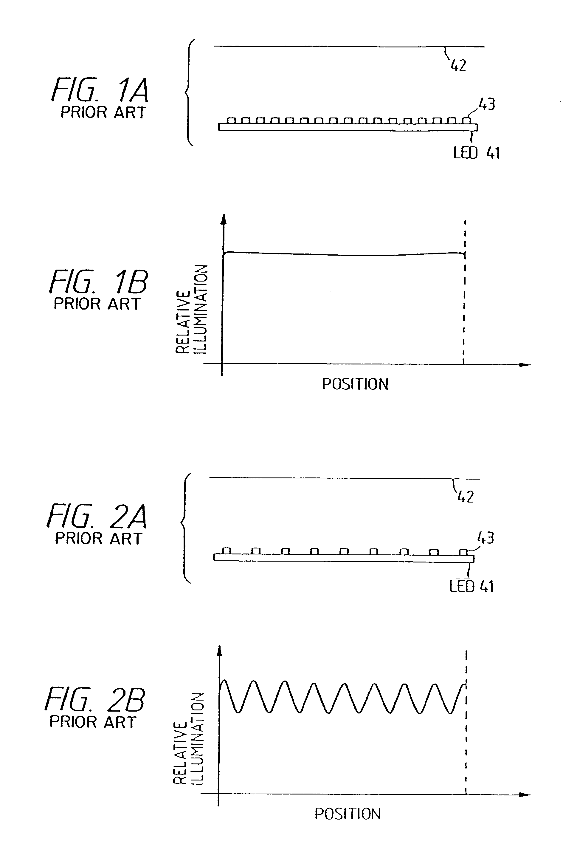
However, because of the increased number of the LED chips, it is difficult to achieve a sufficiently low cost, and to reduce the power consumption beyond a certain limit even though the power required for an individual LED is quite low.
If the number of LED's in the array is decreased, there results, as shown in FIG. 2B, an extremely uneven illumination state in which the illumination intensity on the original surface is high in positions corresponding to the LED chips but is low in positions corresponding to the gaps between the LED chips.
The precise original reading becomes difficult under such an illumination intensity distribution, and a circuit is required to compensate for the unevenness in the illumination intensity distribution, eventually leading to a higher cost.
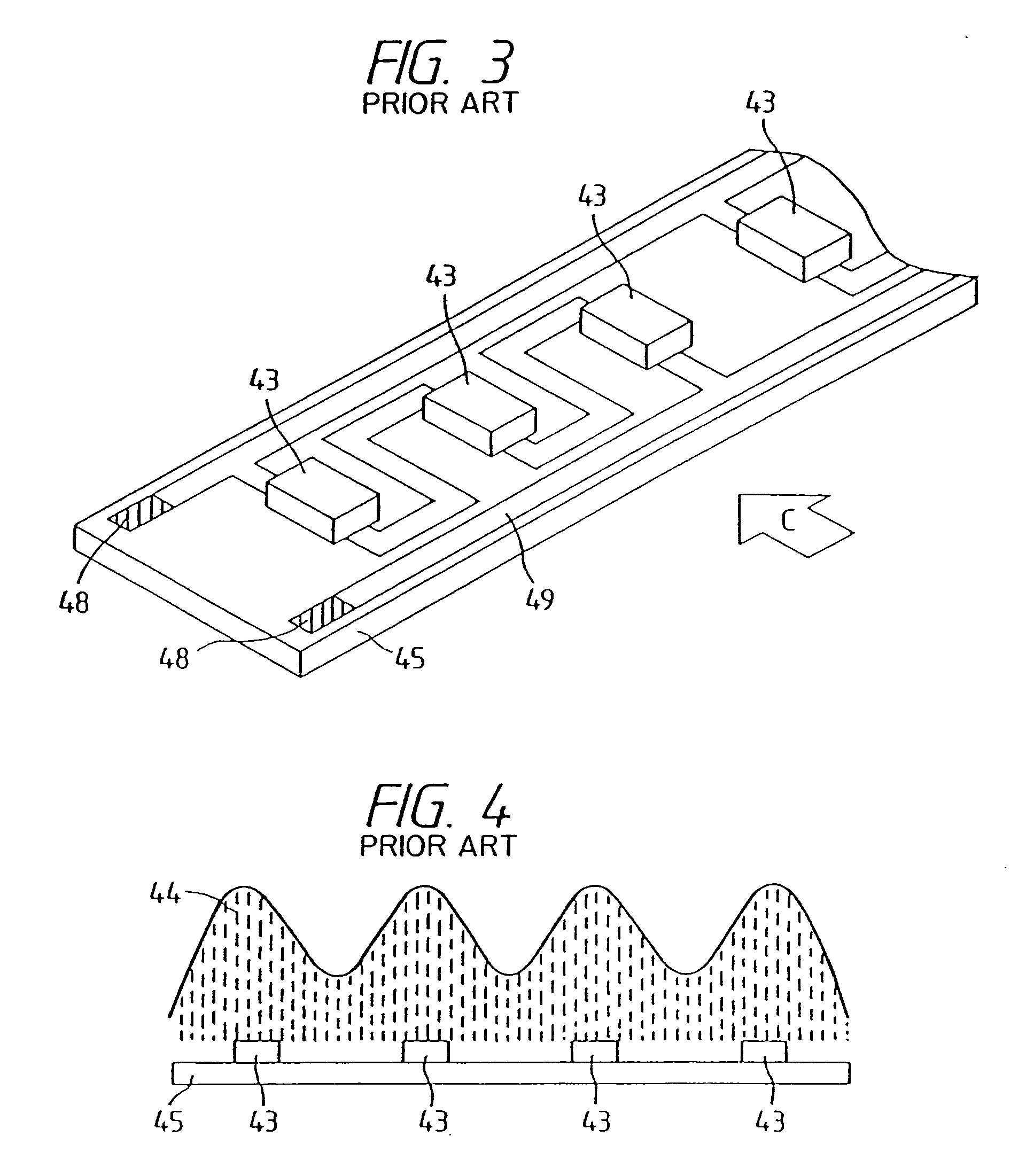
As a result, there is formed unevenness in the light amount corresponding to the arrangement of the LED chips 43.
In reading image information with such a linear light source, the reflected light from the illuminated surface also involves unevenness in the light amount similar to that shown in FIG. 4, so that a large burden is required in the post-process such as image processing for improving the tonal rendition.
However, the use of the light bulb is associated with the drawbacks of a large electric power consumption in return for a high illumination intensity, difficulty in compactization of the device because of the large heat generation, and lack of maintenance-free character as in the case of LED's, since the electric light bulb has a service life considerably shorter than even that of the fluorescent lamp and has to be replaced when the light amount becomes low or when the filament is broken.

Method used


Image

  • Light guide, illuminating device having the light guide, and image reading device and information processing apparatus having the illuminating device
  • Light guide, illuminating device having the light guide, and image reading device and information processing apparatus having the illuminating device
  • Light guide, illuminating device having the light guide, and image reading device and information processing apparatus having the illuminating device

Examples


embodiment 1

[0103]FIG. 10 is a perspective view showing an embodiment 1 of the linear light source of the present invention, wherein shown are an oblong transparent (translucent) member 3, substrates 45; LED chips 71 mounted on the substrates 45, and a light emitting direction 11. A lateral face 3a of the transparent member 3 constitutes the light emitting face, while other lateral faces 3b, 3c and 3d are formed as mirror faces to constitute light reflecting faces.

[0104] The oblong transparent member 3 is provided at both ends thereof with the LED chips 71 constituting the light sources, and the light therefrom enters the transparent member 3 from the end faces thereof and is emitted from the lateral face 3a in the direction 11 either directly or after reflection on the lateral faces 3b, 3c, 3d. In this embodiment, the lateral face 3d is tapered so that the transparent member 3 has a smaller cross section at the center, whereby the light can be efficiently reflected in the direction 11. In thi...

embodiment 2

[0106]FIG. 12 shows the elevation view of an embodiment 2 of the linear light source of the present invention, seen from the direction A shown in FIG. 10, and the light amount distribution on an illuminated surface (not shown). Components that are the same as those shown in FIGS. 10 and 11 are represented by the same numbers and will not be explained further.

[0107] In the present embodiment, the lateral face 3d of the oblong transparent member 3 is tapered so as to reduce the cross section thereof at the center as in Embodiment 1, and the transparent member 3 is formed so as to have a trapezoidal cross section having the shorter side at the light emitting face and the longer side at the opposite face. Such a trapezoidal cross section, as shown in FIG. 12, allows the light to be emitted in the transparent member 3, in a more condensed state, into the direction 11, thereby increasing the illumination intensity on the illuminated surface, in comparison with Embodiment 1, within the ar...

embodiment 3

[0108]FIG. 14 is a plan view of an embodiment 3 of the linear light source of the present invention, seen from a direction B shown in FIG. 10, and FIG. 16 shows the elevation view of the embodiment seen from a direction B shown in FIG. 10 and the light amount distribution. Components that are the same as those shown in FIGS. 10 and 11 are represented by the same numbers and will not be explained further.

[0109] As shown in FIG. 14, the oblong transparent member 3 of this embodiment is provided, in the vicinities of the light sources on the light emitting lateral face 3a, with light attenuating films 306, which attenuate the light emitted from the vicinity of the light sources, thereby providing a light amount distribution, as shown in FIG. 16, on the illuminated surface.

[0110] The attenuating films 306 may be replaced by light shielding films 307 for reducing the light amount in the vicinity of the light source. FIG. 15 is a plan view showing an example in which the light shielding...


PUM


Abstract

In an illumination device, a light guide is adapted to emit the light from a face thereof and is provided with an area, on a face opposite to the light emitting face, for diffusing and / or reflecting the light introduced into the light guide from an end face thereof or is provided with uneven light emitting characteristics along the longitudinal direction of the light guide, and the center of the light source positioned at the end of the light guide is placed at a position aberrated from the normal line to the area, whereby attained are compactness, a low cost, a low electric power consumption, a high efficiency of utilization of the light emitted by the light source, and excellent and uniform illumination characteristics. An image reading device and an information processing apparatus can also be equipped with the above-mentioned illumination device.

Description

[0001] This application is a divisional application of application Ser. No. 10 / 295,925, filed Nov. 18, 2002, which is a continuation of application Ser. No. 08 / 948,661, filed Oct. 10, 1997, now U.S. Pat. No. 6,512,600, which is a divisional application of application Ser. No. 08 / 471,756, filed Jun. 6, 1995, now abandoned, which is a divisional application of application Ser. No. 08 / 183,367, filed Jan. 19, 1994, now U.S. Pat. No. 5,499,112, the entire contents of all of which are incorporated herein by reference.BACKGROUND OF THE INVENTION [0002] 1. Field of the Invention [0003] The present invention relates to a light guide, an illuminating device having the light guide, and an image reading device and an information processing apparatus having the illuminating device, and more particularly an information processing apparatus (such as a copying machine, a facsimile apparatus, a scanner or an electronic blackboard), an image reading device adapted for use in such an information proce...

Claims


Application Information

Patent Timeline
Patent Type & Authority Applications(United States)
IPC IPC(8): H04N1/00F21V8/00G02B6/00G02B6/04G02B6/10G02B6/42H04N1/028H04N1/03H04N1/031
CPCG02B6/0001G02B6/0013H04N2201/03112H04N1/0318H04N1/0316H04N1/0313G02B6/0031G02B6/0036G02B6/0038G02B6/0043G02B6/0046G02B6/0055G02B6/0061G02B6/10G02B6/42G02B2006/0098H04N1/02815H04N1/0282H04N1/02835H04N1/0284H04N1/02885H04N1/0289H04N1/03H04N2201/03125H04N2201/03129H04N2201/03141H04N2201/03145G03G15/04
Inventor KAWAI, TATSUNDOHAMAMOTO, OSAMUTAKEDA, SHINICHIITABASHI, SATOSHIISO, TOSHIMITSU
Owner CANON KK
Learn More