Eureka AIR delivers breakthrough ideas for toughest innovation challenges, trusted by R&D personnel around the world.

Diffractive imaging system and method for the reading and analysis of skin topology

a diffractive imaging and topology technology, applied in the field of diffractive imaging system and method for reading and analysis of skin topology, can solve the problems of reducing the usefulness of real-life applications of optical designs for fingerprint images, many designs are not suitable, and most optical designs are proposed for fingerprint images

Active Publication Date: 2006-06-08
APRILIS
View PDF8 Cites 126 Cited by
  • Summary
  • Abstract
  • Description
  • Claims
  • Application Information

AI Technical Summary

Benefits of technology

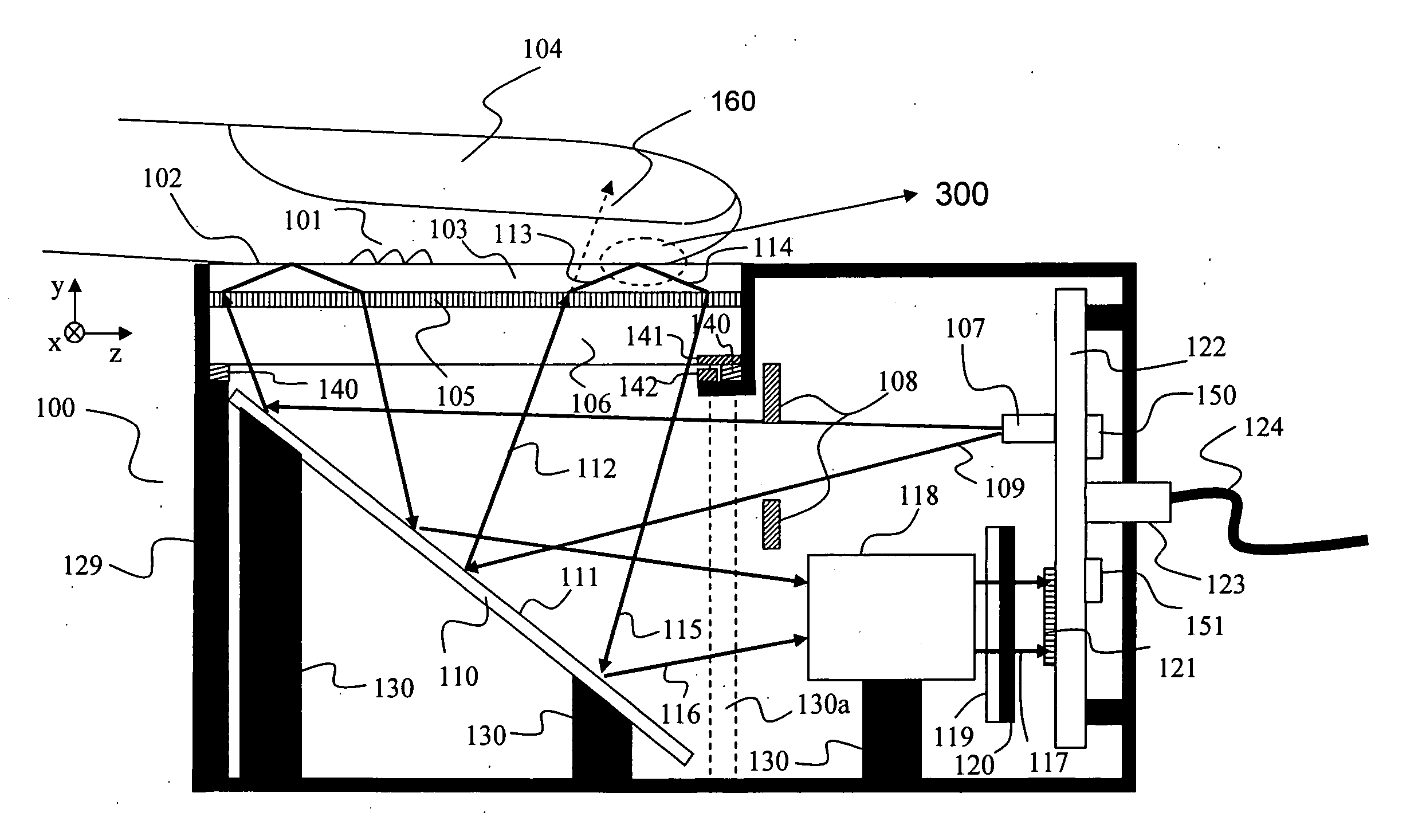
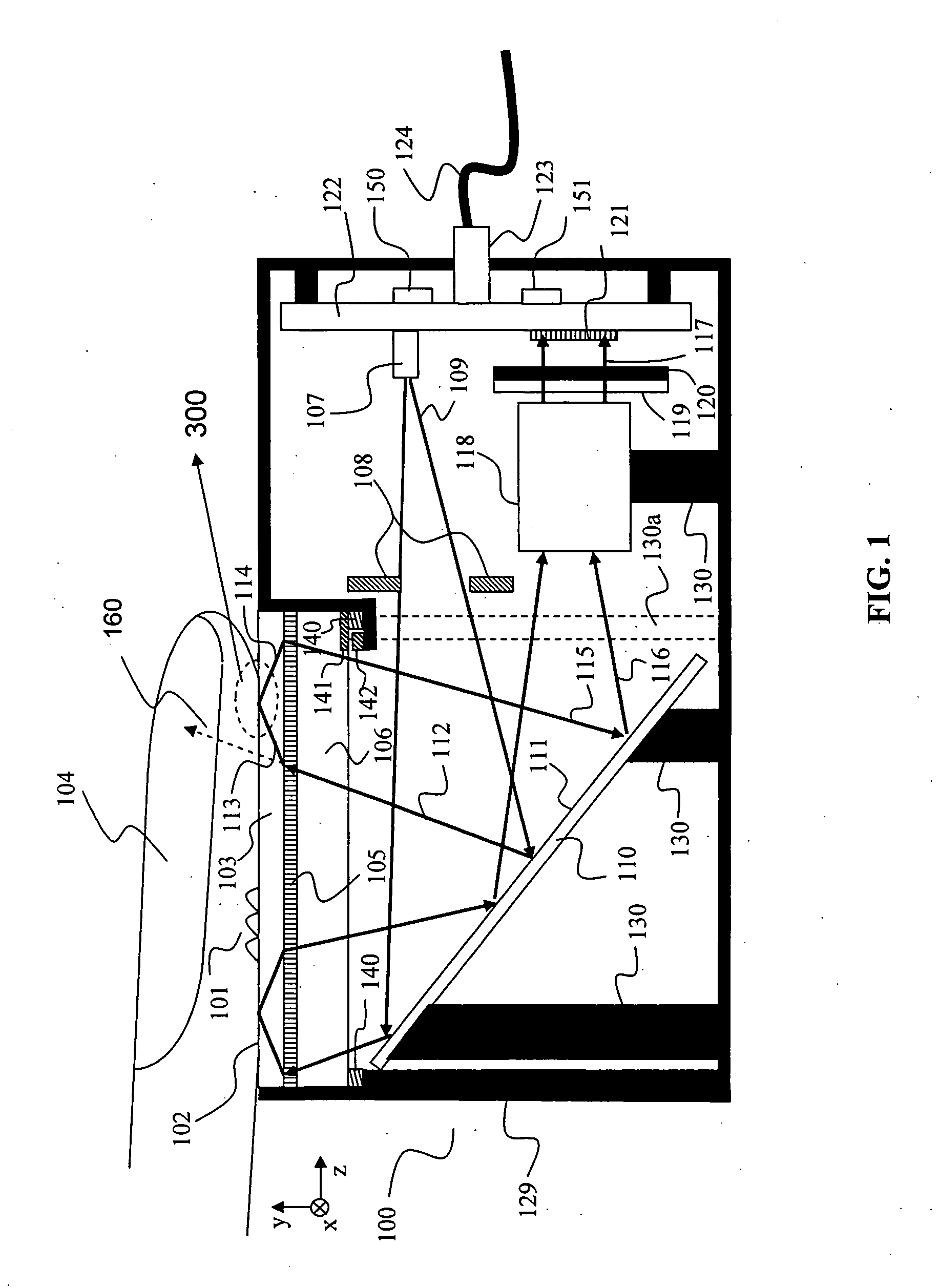
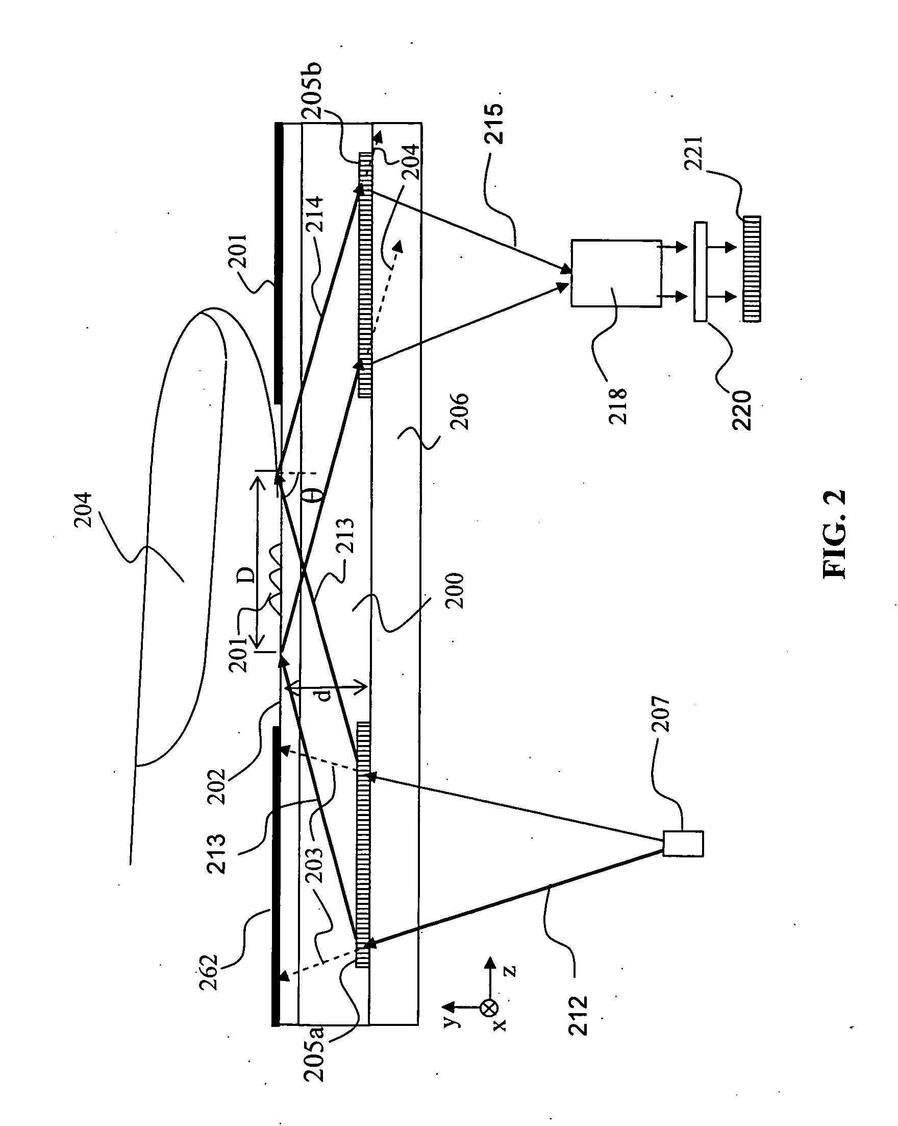
[0015] The apparatus and the method of the instant invention produce undistorted images of high resolution by employing a compact design. Specifically, the apparatus of the present invention produces a high-contrast, high-resolution image by illuminating the image surface at a shallow angle, thus inducing total internal at the interface of the imaged surface and the surface that the imaged surface is in contact with. Apparatus of the present invention is portable and can work in a wide range of temperatures due to employing diffractive holographic optical elements.

Problems solved by technology

Most optical designs proposed for creating fingerprint images suffer important limitations that reduce their usefulness in real life applications.
Many designs are not suitable, for example, to resolve pore patterns or fine detail of the contour of the intersection of ridges and valleys in the fingerprint.
Other designs produce distorted images that complicate fingerprint correlation, such as due to trapezoidal distortions, or due to presence of latent fingerprints, or due to the presence of moisture on the skin surface, and still other designs are too bulky or delicate for convenient use in the field.

Method used


Image

  • Diffractive imaging system and method for the reading and analysis of skin topology
  • Diffractive imaging system and method for the reading and analysis of skin topology
  • Diffractive imaging system and method for the reading and analysis of skin topology

Examples


example 1

Optical Imaging Performance of the Imaging Apparatus Depicted in FIG. 4

[0092]FIG. 6A and FIG. 6B illustrate the optical imaging performance of one embodiment of the imaging apparatus depicted in FIG. 4. In this embodiment, substrates 460, 462, 468 and 466 were modeled as BK7 glass with thicknesses of 1.6, 1.6, 1.6, and 0.6 mm, respectively. The device was designed to achieve 1200 ppi electronic resolution with the use of an Eastman Kodak (Rochester, N.Y.) CMOS chip KAC-9648 (1288×1032 array of 6×6 μm pixels). The custom imaging optics have the prescription as shown in Table 1.

TABLE 1Imaging Optics for Performance denoted by FIGS. 6A and 6B.Lens ElementMaterialParameters (mm)1LAK10R1 = 9.324R2 = −23.875T = 3.767Air gapAirT = 0.6352SF8R1 = −13.760R2 = 5.425T = 1.259Air gapAirT = 5.2063SK16R1 = −1555.9R2 = −8.637T = −8.637

[0093] The optical system was analyzed observing the performance of the system at field points with coordinates of 10.84 and 13.55, as these represents half of the ...

example 2

Optical Imaging Performance of the Imaging Apparatus Depicted in FIG. 4

[0094]FIG. 7A and FIG. 7B illustrate the optical imaging performance of one embodiment of the imaging apparatus depicted in FIG. 4. In this embodiment, by use of a custom set of imaging optic 418, the imaging apparatus is capable of passing AFIS Image Quality Specifications for 1000 ppi. The substrates 460, 462, 468 and 466 were modeled as per above for BK7 glass with thicknesses of 1.6, 1.6, 1.6, and 0.6 mm, respectively. The custom imaging optics have the prescription as shown in Table 2.

TABLE 2Imaging Optics for Performance denoted by FIGS. 7A and 7B.Lens ElementMaterialParameters (mm)1LAK10R1 = 9.265R2 = −18.779T = 3.767Air gapAirT = 0.6352SF8R1 = −11.523R2 = 5.649T = 1.259Air gapAirT = 5.2063SK16R1 = 1787.14 (cyl.)R2 = −8.916T = −4.709

[0095]FIG. 7A illustrates the distortion of the. The maximum distortion is 0.77% which slightly exceeds the AFIS Level 2 specification for a 1000 ppi fingerprint scanner that...

example 3

Fingerprints Taken with the Apparatus Depicted in FIG. 4

[0096] In FIG. 8A and FIG. 8B are images of fingerprints that were taken with the apparatus depicted in FIG. 4. FIG. 8A illustrates the fingerprint at 1200 ppi of a subject that was taken dry (i.e., no moisture added to the finger). The image captured is approximately 27.3×21.8 mm across. In FIG. 8B an image of the same finger was taken under the same conditions as the fingerprint in FIG. 8A with the exception that a saturated salt water solution was poured on skin contact surface 402. FIG. 8B illustrates the apparatus constructed as exemplification of embodiments of the present invention operates at a TIR angle that is higher than the TIR angle for float glass to salt water and in this manner fingerprints can still be taken of a substrate with sweaty hands and / or in a very humid environment.


PUM


Abstract

An apparatus and a method for acquiring an image of skin topology. The apparatus comprises at least one light source, configured to form a source beam; at least one illuminating diffractive optical element (DOE) disposed in the optical path of the source beam, configured to diffract the source beam, thereby forming an illuminating beam; a skin contact surface, disposed in the optical path of the illuminating beam, configured to at least partially reflect the illuminating beam at regions of the boundary between the skin contact surface and skin that are not in contact with skin, thereby forming a reflected beam; at least one imaging diffractive optical element (DOE), disposed in the optical path of the reflected beam, configured to diffract the reflected light beam, thereby forming an image beam; and a sensor array, configured to receive at least a portion of the image beam and thereby to detect the acquired image.

Description

RELATED APPLICATIONS [0001] This application claims the benefit of U.S. Provisional Application No. 60 / 619,459, filed on Oct. 15, 2004. The entire teachings of the above application are incorporated herein by reference.BACKGROUND OF THE INVENTION [0002] Growing concerns regarding domestic security have created a critical need to positively identify individuals as legitimate holders of credit cards, driver's licenses, passports and other forms of identification such as those for the military or drivers of hazardous materials, or school teachers, etc. The ideal identification process is reliable, fast, and relatively inexpensive. [0003] A well-established method for identification is to compare a fingerprint with a previously obtained authentic fingerprint of the individual. Fingerprints have traditionally been collected by rolling an inked finger on a white paper. Attempts to employ an electronically imaged fingerprint method use, as a key component, a solid-state device such as a ca...

Claims


Application Information

Patent Timeline
IPC IPC(8): G06K9/74
CPCA61B5/1172G06K9/00046G06V40/1324
Inventor RAGUIN, DANIEL H.WALDMAN, DAVID A.MALYAK, PHILLIP H.BERG, JOHN S.INGWALL, RICHARD T.
Owner APRILIS
Why Eureka
Eureka Blog
Learn More