
Height-adjustable support for semitrailers or the like

a technology of height adjustment and semi-trailers, applied in the direction of machine supports, vehicle maintenance, furniture parts, etc., can solve the problems of inability to follow the foot plates of the support, the axle region may drop, and the longitudinal thrust, etc., to achieve cost-effective production

Inactive Publication Date: 2006-06-08
GEORG FISCHER VERKEHRSTECHNIK GMBH
View PDF8 Cites 10 Cited by
  • Summary
  • Abstract
  • Description
  • Claims
  • Application Information

AI Technical Summary

Benefits of technology

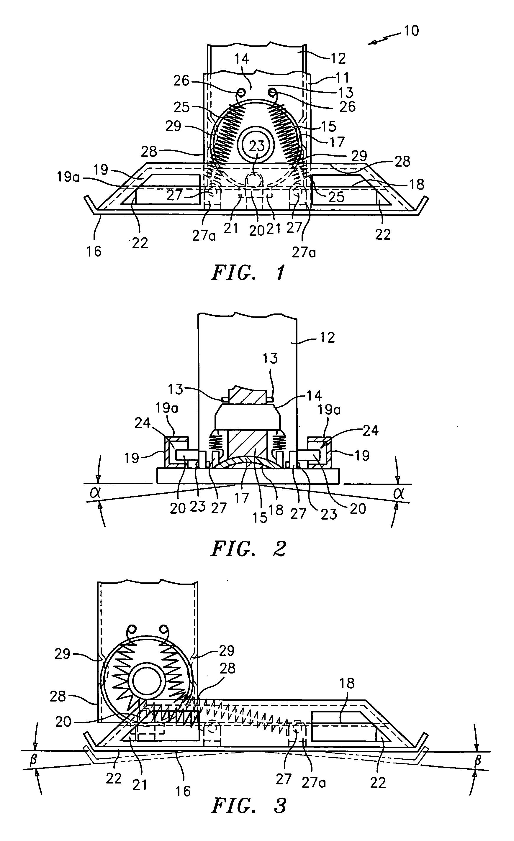
[0007] This solution has the advantage that the tension springs in the basic position of the support, i.e. both during transportation and when parked, in a resting supporting function, are situated entirely within the inner support tube in a manner protected against dirt and the weather and are only partially exposed only during a thrust compensation of the support. In an advantageous manner, the retaining device between the foot plate and the inner support tube is designed in such a manner that it is generally not in engagement. The foot plate is therefore pivotable to a sufficient extent both about its transverse axis and about its longitudinal axis. This pivotability on all sides with the possibility (which advantageously exists as a result) of adapting the foot plate to sloping ground is also ensured by the installation of a track roller, with a preferably cross-sectionally circular-arc-shaped concave track groove, into the inner support tube and a rolling track, of complementarily convex design with respect to the track groove of the track roller, on the foot plate. In contrast to a bar which conventionally penetrates a rolling segment and the side walls of the foot element and therefore, by means of tilting, prevents the foot element and the like from being adapted to the ground, in the case of the retaining device proposed there is absolutely no contact with other parts even when the foot plate is sufficiently pivoted transversely. The retaining device only comes into action if the tension springs should accidentally break at the same time, and it then brings about a secure interlocking of the foot plate with the inner support tube, so that the foot plate cannot be lost.
[0010] Finally, it is advantageous to provide deflecting runners in the inner support tube, which deflecting runners gently deflect the tension springs, which are extended during the thrust compensation of the support. Also in an advantageous manner the deflection angles which arise in the process result in favourable spring force components during the resetting of the foot plate by the tension springs. It is particularly cost-effective to produce, i.e. to impress, the deflecting runners by means of a corresponding impressing of the shape in those wall portions of the inner support tube which are situated in the regions of the tension springs.

Problems solved by technology

In the case of the semitrailers which are prevalent nowadays and have air-sprung axles, the axle region may drop during relatively long parked periods because of pressure losses in the air spring bellows.
In this case, with the axle assembly generally braked during parking, the semitrailer is subjected to a longitudinal thrust forwards, which the foot plates of the support are incapable of following because of adherence to the ground.
In this situation, the supports with rigid foot plates would be exposed to a high flexural and buckling stress which might result in them being damaged.
In the direction of the end side, the helical springs are arranged such that they are exposed centrally with respect to the foot plate and are therefore permanently exposed without protection to the weather, which may result in corrosion damage and cause malfunctions.
In this case the width of the rolling segment exceeds the width of the support and, due to the unfavourably great height of this supporting foot and the arrangement of its pivot axle, necessarily on the lowermost end region of the inner support tube, a semitrailer support provided in such a manner obtains a disadvantageous, large construction height.
In addition, this supporting foot is pivotable only in one plane and cannot compensate in the transverse direction for any unevennesses of the ground, which may result in overstressing of the material in the case of uneven parking surfaces.
In addition, after its suspension means are released, a foot of this type could be completely lost.

Method used


Image

  • Height-adjustable support for semitrailers or the like
  • Height-adjustable support for semitrailers or the like
  • Height-adjustable support for semitrailers or the like

Examples


Embodiment Construction

[0018] The supports 10 which are arranged in pairs on the front lower side and symmetrically to the longitudinal axis of the semitrailer (not shown here) each have a vertical outer support tube 11, which is connected to the semitrailer frame, and an inner support tube 12, which is arranged displaceably in said outer support tube, the cross sections of which tubes are generally square. The support tube 12 can be mechanically extended and retracted, i.e. can be brought from the transporting position into the working position by extension or from the working position into the transporting position by retraction.

[0019] Fastened in the lower end region of the inner support tube 12, in the direction looking at FIG. 1, i.e. transversely to the direction of travel of the semitrailer, are two spaced-apart, aligned bearing housings 13 in which a cylindrical axle 14 is fixed. A track roller 15 is mounted rotatably on the axle 14 and, when the inner support tube 12 is extended, transmits the l...


PUM


Abstract

A height-adjustable support for semitrailers wherein the foot plate is suspended on tension springs which are arranged in two parallel planes situated in each case between the track roller and the wall of the inner support tube, and is fastened to the foot plate by one eyelet in each case in the inner support tube and the other eyelet in the vicinity of the transverse axis, and in that the foot plate corresponds with the inner support tube by means of a retaining device which is not permanently in engagement.

Description

BACKGROUND OF THE INVENTION [0001] The invention relates to a height-adjustable support for semitrailers. [0002] Supports of this type, usually arranged in pairs, are arranged in the front region of the semitrailer. A respective supporting foot with a foot plate, on which at least one rolling element rolls, is situated at the lower end of the extendible inner support tubes. The supports are used whenever the semitrailer is parked separately from the articulated lorry. In the case of the semitrailers which are prevalent nowadays and have air-sprung axles, the axle region may drop during relatively long parked periods because of pressure losses in the air spring bellows. In this case, with the axle assembly generally braked during parking, the semitrailer is subjected to a longitudinal thrust forwards, which the foot plates of the support are incapable of following because of adherence to the ground. In this situation, the supports with rigid foot plates would be exposed to a high fle...

Claims


Application Information

Patent Timeline
IPC IPC(8): B60D1/66
CPCB60S9/04
Inventor RIEDL, REINHOLD
Owner GEORG FISCHER VERKEHRSTECHNIK GMBH
Learn More