
Ventilation controller

a technology of ventilation controller and ventilation system, which is applied in the direction of ventilation system, domestic cooling apparatus, heating types, etc., can solve the problems of difficult to properly set up or adjust a conventional ventilation system to meet the requirements of housing or small residential buildings, and tight sealing homes or buildings may create a stale indoor atmosphere, etc., to achieve the effect of convenient configuration

Active Publication Date: 2006-06-08
TRANE INT INC
View PDF25 Cites 114 Cited by
  • Summary
  • Abstract
  • Description
  • Claims
  • Application Information

AI Technical Summary

Benefits of technology

[0012] A primary object of the invention is to provide a ventilation blower that is easily configured by inputting a setting that reflects a building's floor square footage and the number of bedrooms.

Problems solved by technology

In some cases, a tightly sealed home or building may create a stale indoor atmosphere due to an inadequate exchange of indoor and outdoor air caused by a lack of forced or natural ventilation.
Although sophisticated ventilation systems can be custom designed and configured for specific commercial and industrial buildings, such an approach may be impractical for homes or smaller residential buildings that may be no more than three stories above ground.
Even after determining the ventilation airflow requirements of a particular home, it may be difficult to properly set up or adjust a conventional ventilation system to meet those requirements.
First, the Honeywell system relies on the building's main HVAC blower for drawing ventilation air into the building.
Since such a blower is normally much larger than that which would be needed for ventilation alone, energy is wasted during periods when only ventilation is needed.
Later, during normal operation, the blower's volume may change from what it was during calibration, thus the actual ventilation rate may be off significantly.
Third, it does not appear that the Honeywell system accounts for changes in the static pressure differential between the indoor and outdoor air.

Method used


Image

  • Ventilation controller
  • Ventilation controller
  • Ventilation controller

Examples


Embodiment Construction

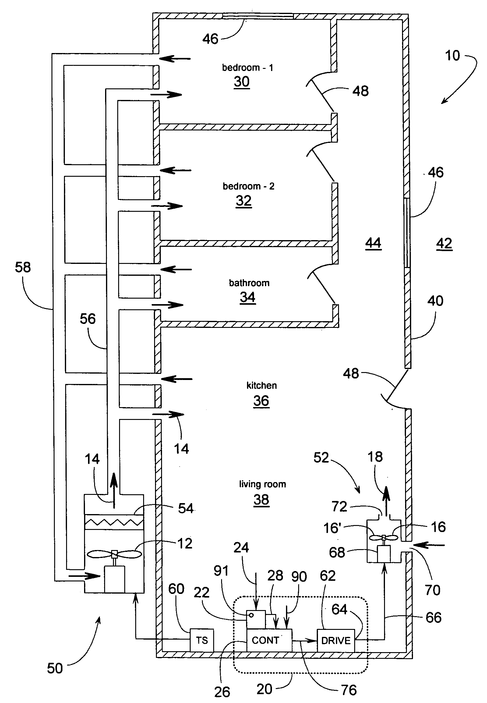
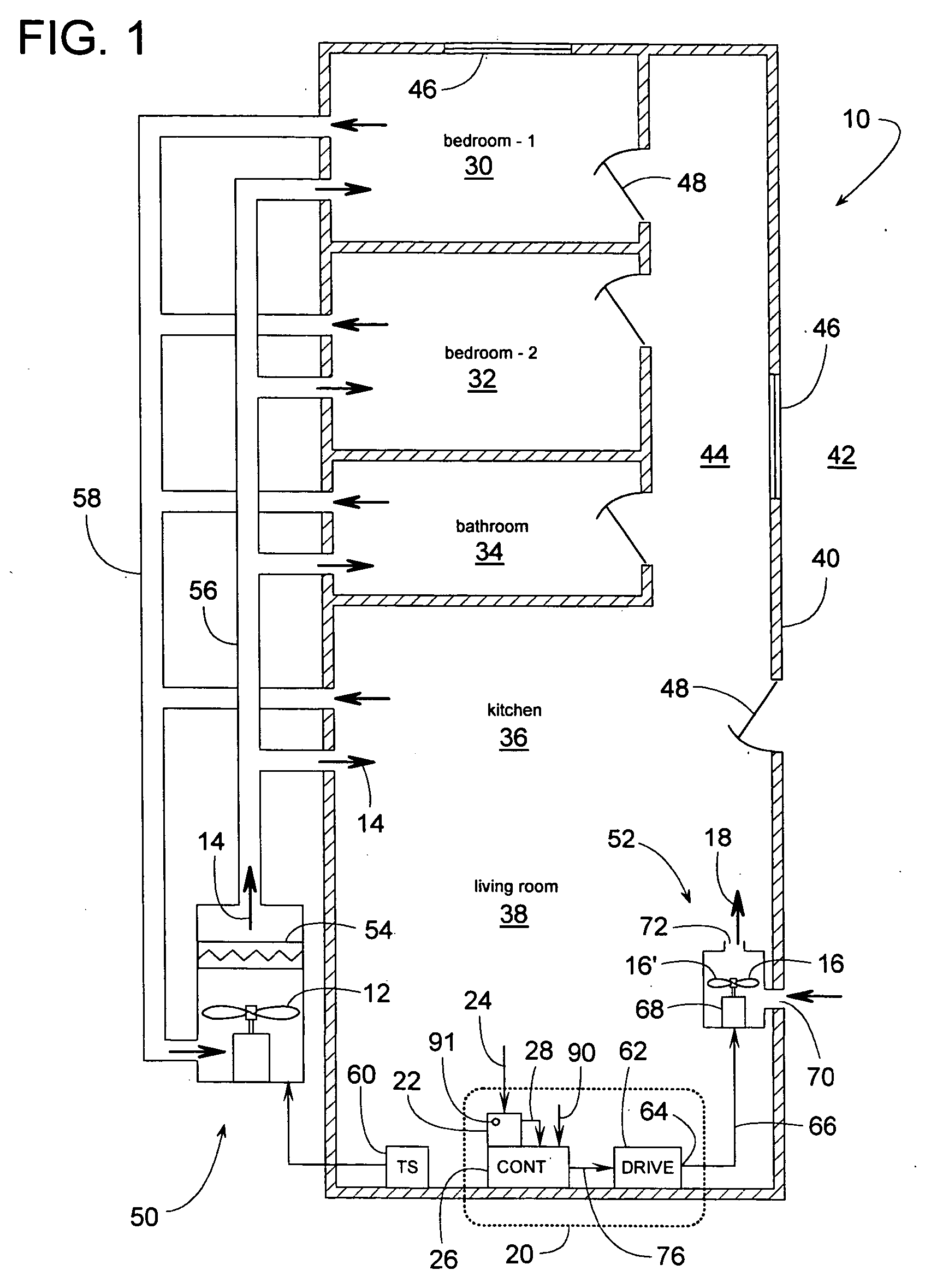
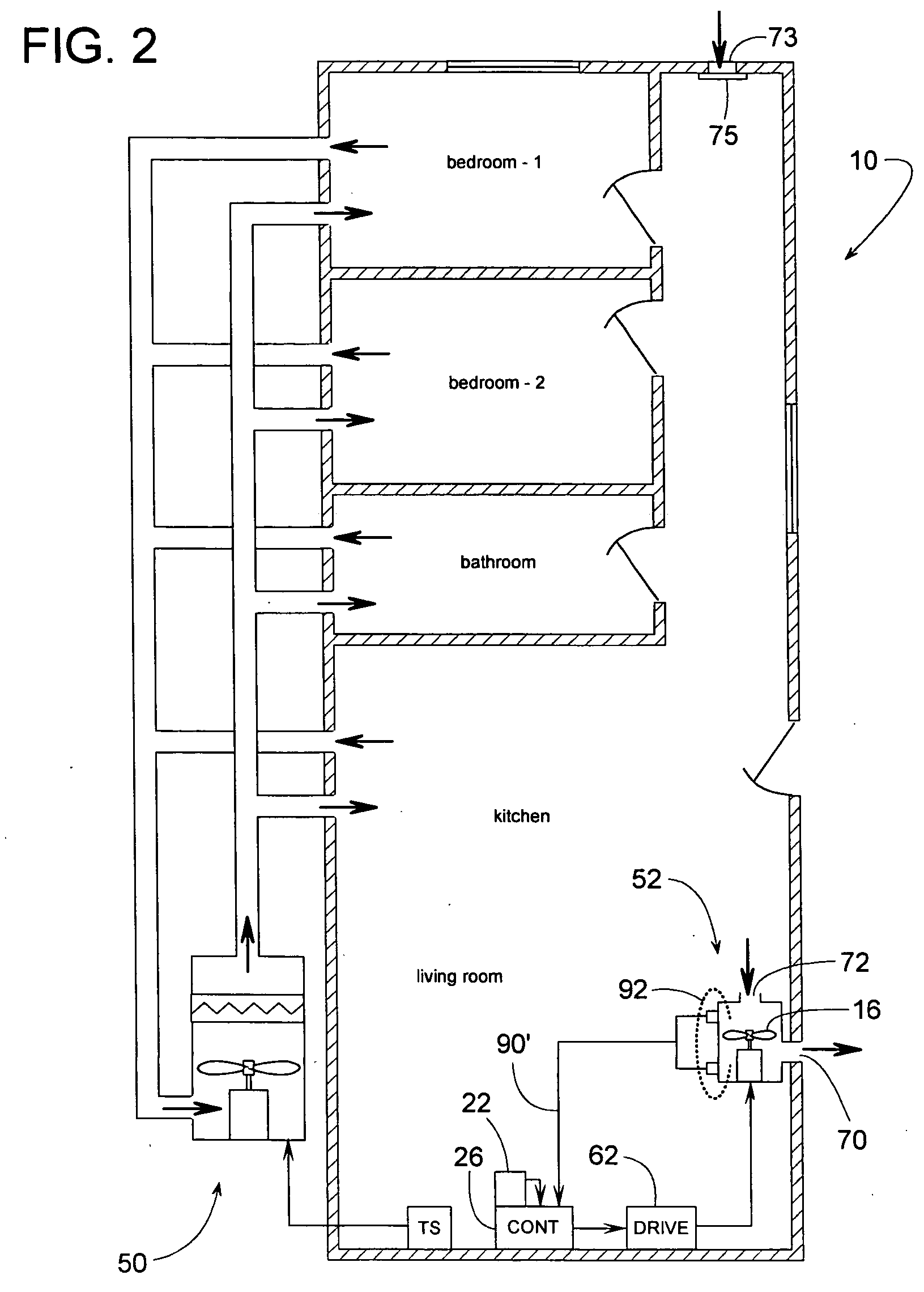
[0041]FIG. 1 schematically illustrates a building 10 that includes a main HVAC blower 12 for moving temperature-conditioned air 14 through the building and a smaller ventilation blower 16 for providing the building with adequate fresh air ventilation. To ensure that blower 16 delivers ventilation air 18 at a target ventilation flow rate or an equivalent average target airflow rate that is appropriate for the size and design of building 10, the flow delivery of blower 16 can be regulated by a control system 20. Control system 20 includes an input 22 for manually entering a ventilation setting 24, which in turn is communicated to a controller 26 via a setup signal 28. Ventilation setting 24 and its corresponding setup signal 28 reflect a specified number of bedrooms and a specified amount of floor space of building 10. The term, “specified” refers to a quantity (e.g., one bedroom, two bedrooms, three bedrooms, 1,000 square-feet, 2,000 square-feet, etc.) as determined by the discretion...


PUM


Abstract

A ventilation system for a building in some cases includes a main HVAC blower for moving temperature-conditioned air through the building plus a smaller ventilation blower for providing fresh air. A controller regulates the ventilation blower's speed to provide a target ventilation flow rate regardless of changes in the pressure differential between the indoor and outdoor air. To ensure that the target rate is appropriate for a particular building, the target flow rate is determined based on a ventilation setting that reflects a specified number of bedrooms and a specified amount of floor space of the building.

Description

BACKGROUND OF THE INVENTION [0001] 1. Field of the Invention [0002] The subject invention generally pertains to the ventilation of buildings and more specifically to a ventilation system that delivers a generally constant airflow rate regardless of changes in the pressure differential between the indoor and outdoor air. [0003] 2. Description of Related Art [0004] Heating ventilating and air conditioning systems, or HVAC systems, often include a blower and a heat exchanger for providing air that is heated, cooled, dehumidified, or conditioned in some way to meet the needs of a building and its occupants. Supply air ductwork can be used for conveying the conditioned air to various rooms of the building. After the conditioned air (supply air) enters and circulates through the rooms, the blower draws the used air (return air) back out of the rooms via a network of return air ducts. The blower then forces the air back across the heat exchanger for reconditioning. [0005] In some cases, a ...

Claims


Application Information

Patent Timeline
IPC IPC(8): F24F7/00F25D29/00F25D17/00F25D23/12
CPCF24F11/0001F24F11/0034F24F11/0017F24F2011/0006Y02B30/746F24F11/0079F24F11/30F24F2110/50F24F2120/10F24F11/77Y02B30/70F24F11/46F24F11/75F24F7/007
Inventor HELT, ROBERT W.CRAWFORD, ROY R.
Owner TRANE INT INC
Learn More