Fastening device

a technology of fastening device and cradle, which is applied in the field of fastening device, can solve the problems of not being able to attach a holster or carrier to a person dressed in such attire, falling into the water, and being sat on, knocked onto the ground and stepped on, etc., and achieves the effect of being easily attached and detachabl

Inactive Publication Date: 2006-06-01
SHANNON EUGENE E +1
View PDF13 Cites 7 Cited by
  • Summary
  • Abstract
  • Description
  • Claims
  • Application Information

AI Technical Summary

Benefits of technology

[0006] Briefly, the novel fastening device of the present invention meets the aforementioned needs of the prior art. The fastening device comprises two pieces. There is a first or female portion and means for fastening the first portion to a person, a pole, or any other surface, no matter where located, to safely and securely mount small electronic devices, tools, cup holders and other items to the first portion. There is a second or male portion that is attached to small electronic devices, tools, cup holders and other items of any kind, and the second portion is easily attachable to and detachable from the first portion to safely and securely mount them to the first portion.

Problems solved by technology

There is a disadvantage that such cellular telephones and other electronic devices are small and too often become misplaced, sat on, knocked onto the ground and stepped on, or fall into the water, especially when the telephone or other small device is located on a patio, poolside, on a boat, on an recreational vehicle, or in a vehicle and is not carried in a holster or other carrier attached to a person' attire or to a supporting surface.
There is no way to attach a holster or carrier to a person dressed in such attire.
These existing holsters or cradles do not work in locations and situations such as described in the previous paragraph.
However, too often, such a cup or glass holders are not available or not located in a position that is convenient for a user and they then place these items on various flat surfaces from which they are too easily knocked over, or slide when the boat or recreational vehicle is in motion.
In addition, even when a glass, bottle or can is positioned in such a cup or glass holder, if the container is full and the boat pitches off vertical in a swell from another boat or due to rough water, the contents therein spills because the container does not remain in a vertical position.

Method used


Image

  • Fastening device
  • Fastening device
  • Fastening device

Examples


Embodiment Construction

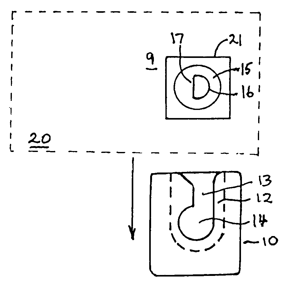
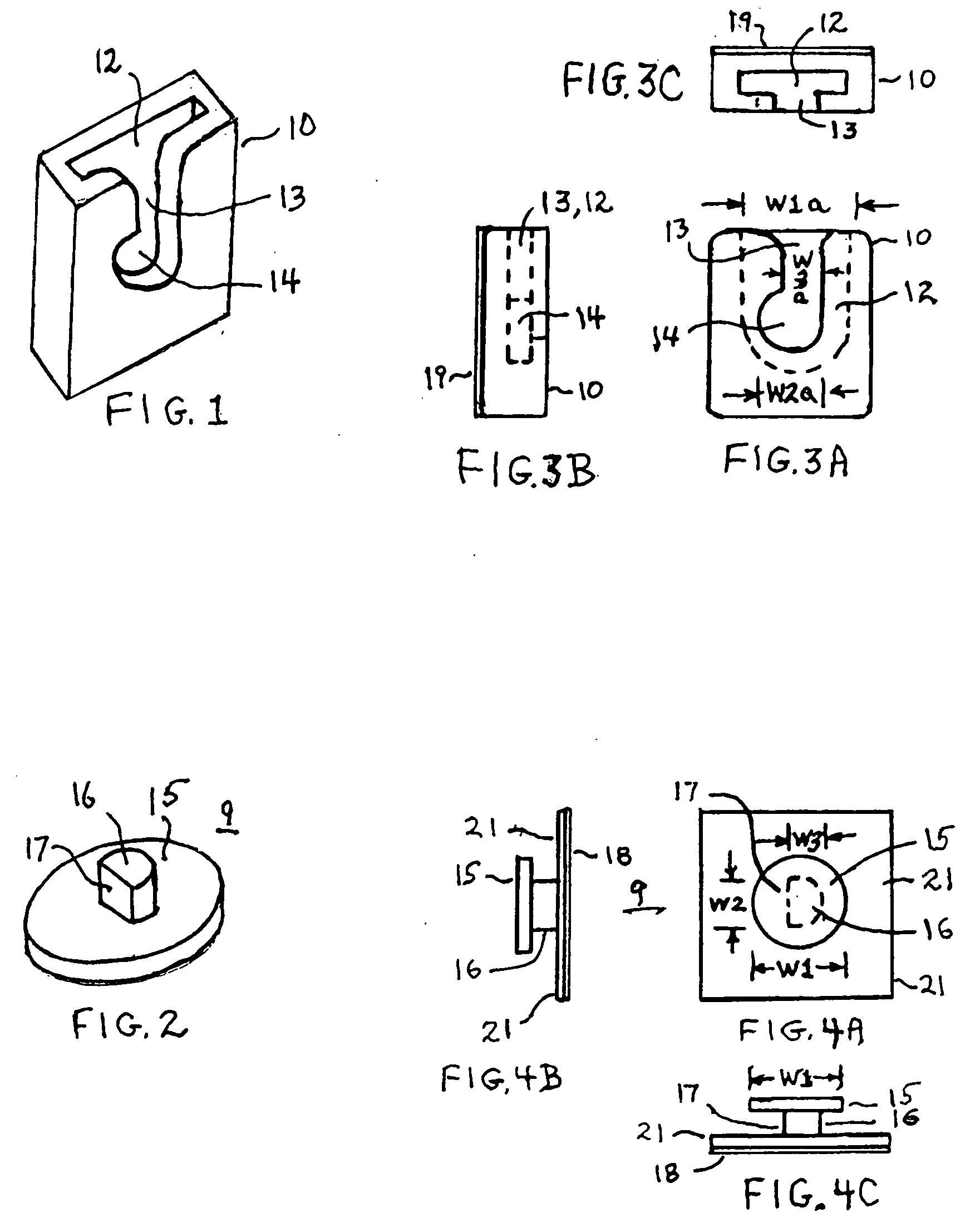
[0022] In FIG. 1 is shown a three dimensional view of the slotted first portion 10 of the fastening device. It comprises a relatively flat member 10 having all open end in which is a flattish hollow area 12 and through one wall of first portion 10 there is a narrow slot 13 with a flared entrance at one end of slot 13 and an offset circular hole 14 at the other end of slot 13. First portion 10 may be manufactured as a discrete, separate piece and attached to a surface using an adhesive to which surface it is desired to attach an electronic device, tool, cup holder or other items; or first portion 10 may be made as an integral part of an another item such as shown in FIGS. 10A and 10B. Details of first portion 10 are shown in greater detail in FIGS. 3A-3C.

[0023] In FIG. 2 is shown a three dimensional view of a mushroom shaped second portion 9 of the novel fastening device. Portion 9 may be manufactured as an integral part of an electronic device, tool, cup holder or other item or it ...


PUM


Abstract

A fastening device is disclosed which consists of a first portion that may be made as an integral part of an object such as small electronic devices, tools or cup holders and other items, or may be separately fastened thereto; and a second portion that may be made as an integral part of some apparel of a user, a supporting structure such as a wall, dash board of a vehicle, a pole, or other surface, or it may fastened thereto. The first portion has a generally keyhole shaped slot having a narrow slot with parallel sides, a flared entrance at one end of the slot, an enlarged hole at the other end of the narrow slot and channel behind the slot and hole. The second portion has a mushroom shape with a stem and a flat, button shaped top. The stem is attached perpendicularly to one side of the top, has a generally circular cross section and has one flat side along the length of the stem. The diameter of the button shaped top is larger than the width of the slot and the diameter of the circular hole and less than the width of the channel. The stem can only pass along the slot into the hole when its flattened side is parallel to a particular side of the slot while the top passes through the channel. When the stem is rotated ninety degrees so that its flat side is oriented perpendicular to the sides of the narrow slot, or parallel to the other side of the slot the stem will not pass back through the slot.

Description

FIELD OF THE INVENTION [0001] This invention relates to a fastening device which permits the attachment and removal of small, portable devices, such as cellular telephones, small electronic devices, tools, and other small items to the apparel of a user, to a supporting structure such as a wall, a dash board of a vehicle, a pole, or the like. BACKGROUND OF THE INVENTION [0002] Cellular telephones and other small electronic devices such as portable radios and music players are commonly used all over the world. There is a disadvantage that such cellular telephones and other electronic devices are small and too often become misplaced, sat on, knocked onto the ground and stepped on, or fall into the water, especially when the telephone or other small device is located on a patio, poolside, on a boat, on an recreational vehicle, or in a vehicle and is not carried in a holster or other carrier attached to a person' attire or to a supporting surface. This is too often the case when people a...

Claims


Application Information

Patent Timeline
Patent Type & Authority Applications(United States)
IPC IPC(8): A45F5/02A44B21/00A44B99/00
CPCA45F5/00Y10T24/1394A45F2200/0525
Inventor SHANNON, EUGENE E.SHANNON, PAUL E.
Owner SHANNON EUGENE E
Why Eureka
Try Eureka