Aircraft brake actuation system and method including anti-hysteresis control

a technology of brake actuation and airframe, which is applied in the direction of process and machine control, instruments, navigation instruments, etc., can solve the problems of hysteresis of the airframe brake actuation system, failure to achieve phase shift in system frequency response, and errors in control accuracy

Active Publication Date: 2006-05-25
HONEYWELL INT INC
View PDF22 Cites 17 Cited by
  • Summary
  • Abstract
  • Description
  • Claims
  • Application Information

AI Technical Summary

Problems solved by technology

An aircraft brake actuation system, like many other control systems, may exhibit hysteresis.
This hysteresis may result from various position control errors and from friction and / or other inefficiencies in various mechanical elements in the system.
For example, in an aircraft brake actuation system the actuators may exhibit gear losses, and some compliance may exist between the actuator power unit (e.g., the motor) and the actuator output.
Moreover, frictional losses and compliance may exist between the actuator output and the brake disk packet, as well as within the brake disk packet itself.
The hysteresis effects due to the various mechanical inefficiency sources are, however, more difficult to address, and can cause errors in control accuracy and a phase shift in system frequency response.

Method used


Image

  • Aircraft brake actuation system and method including anti-hysteresis control
  • Aircraft brake actuation system and method including anti-hysteresis control
  • Aircraft brake actuation system and method including anti-hysteresis control

Examples


Embodiment Construction

[0016] The following detailed description is merely exemplary in nature and is not intended to limit the invention or the application and uses of the invention. Furthermore, there is no intention to be bound by any theory presented in the preceding background of the invention or the following detailed description of the invention. In this regard, before proceeding with the detailed description, it is to be appreciated that the described embodiment is not limited to use in conjunction with a specific vehicle or brake system. Thus, although the description is explicitly directed toward an embodiment that is implemented in an aircraft brake actuation system, it should be appreciated that it can be implemented in other vehicles and other brake actuation system designs, including those known now or hereafter in the art.

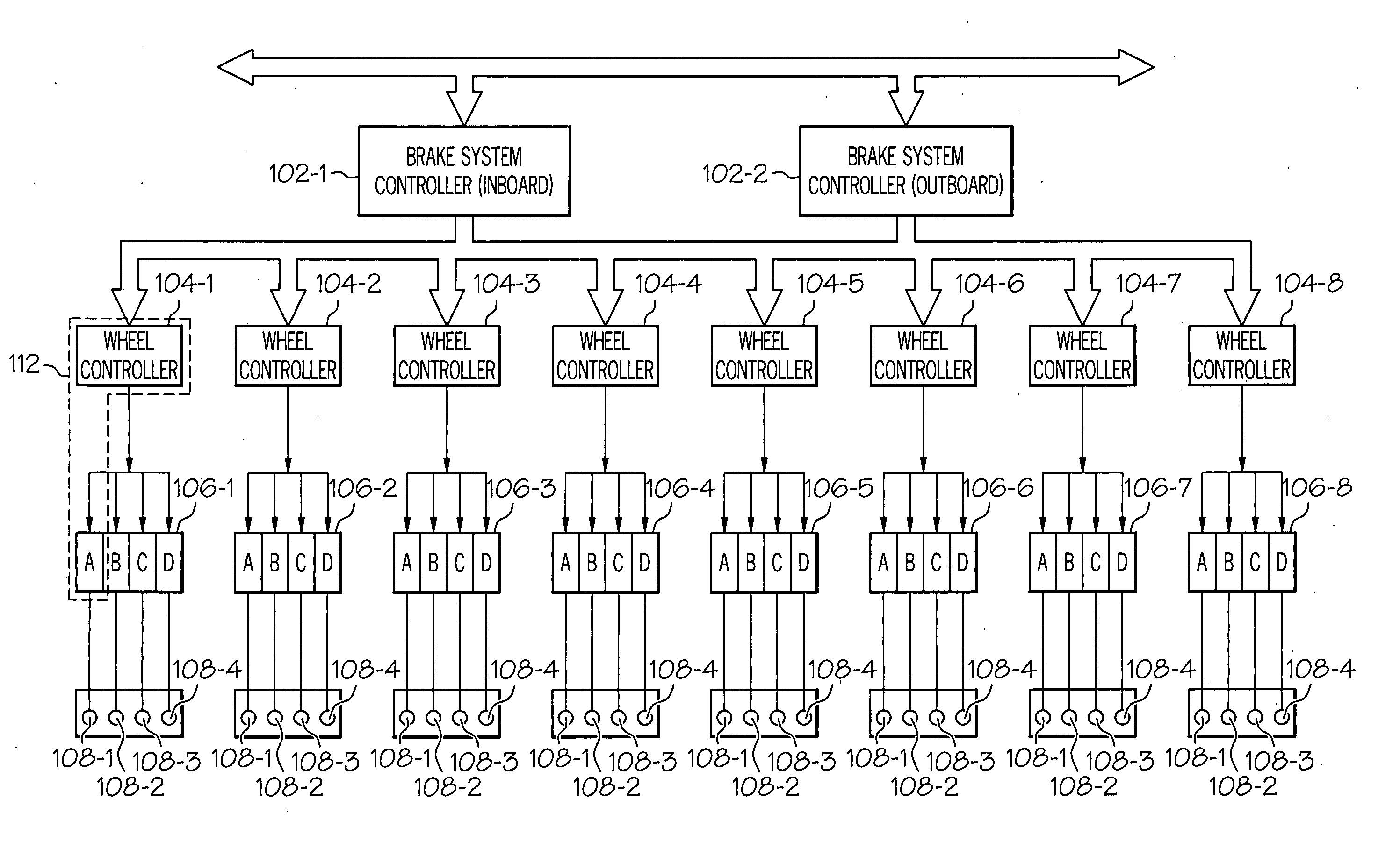
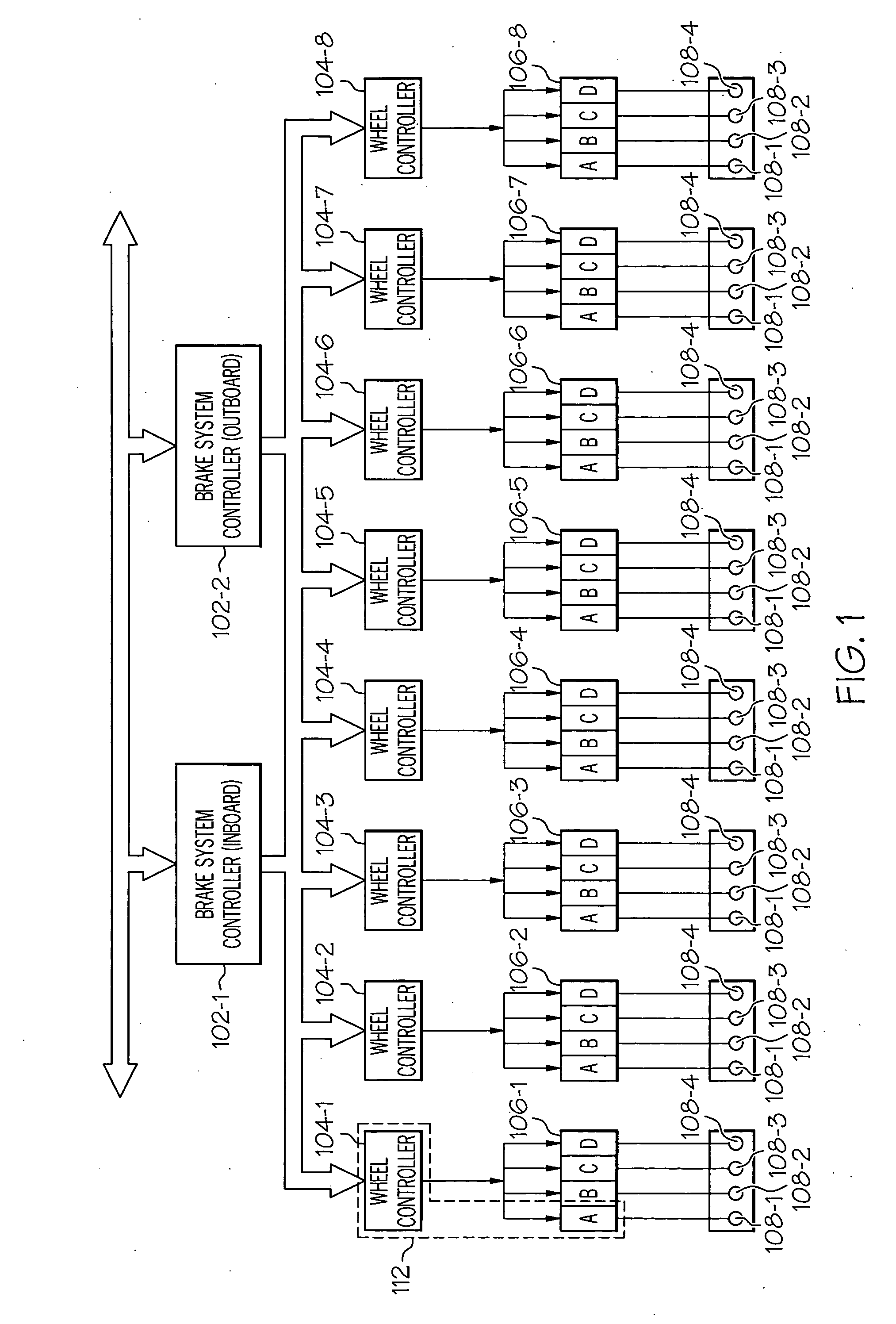
[0017] Turning now to the description, and with reference first to FIG. 1, a functional block diagram of an exemplary aircraft brake actuation system 100 is shown. In the...


PUM


Abstract

An aircraft brake actuation system implements an anti-hysteresis feature that compensates for various hysteresis effects exhibited in an aircraft brake actuation system due to one or more sources of mechanical inefficiency within the system. The anti-hysteresis feature adjusts the command signal up or down, depending on the direction of the command, a predetermined amount based on the amount of hysteresis in the system. By doing so, the actual brake force supplied to the aircraft brake elements more accurately represents the brake force being commanded.

Description

TECHNICAL FIELD [0001] The present invention relates to aircraft brake actuation systems and, more particularly, to a controller for an aircraft brake actuation system that compensates for mechanical hysteresis in the system. BACKGROUND [0002] When a jet-powered aircraft lands, the aircraft brakes, various aerodynamic drag sources (e.g., flaps, spoilers, etc.), and, in many instances, aircraft thrust reversers, are used to slow the aircraft down in the desired amount of runway distance. Once the aircraft is sufficiently slowed, and is taxiing from the runway toward its ground destination, the aircraft brakes are used slow the aircraft, and bring it to a stop at its final ground destination. [0003] Presently, many aircraft brake systems include a plurality of hydraulic, pneumatic, or electromechanical actuators, and a plurality of wheel mounted brakes. The brakes in many aircraft are implemented as multi-disk brakes, which include a plurality of stator disks and rotor disks. The stat...

Claims


Application Information

Patent Timeline
Patent Type & Authority Applications(United States)
IPC IPC(8): B60T8/86
CPCB60T8/1703
Inventor EVANS, PAUL S.QUITMEYER, JAMES N.
Owner HONEYWELL INT INC
Why Eureka
Try Eureka