
Audio spatial environment down-mixer

a spatial environment and downmixing technology, applied in the field of audio data processing, can solve the problems of unpredictable and unsatisfactory, audio data that is processed for optimal audio quality in a first environment is often not readily used in a different audio environment,

Inactive Publication Date: 2006-05-18
DTS
View PDF18 Cites 110 Cited by
  • Summary
  • Abstract
  • Description
  • Claims
  • Application Information

AI Technical Summary

Benefits of technology

[0009] The present invention provides many important technical advantages. One important technical advantage of the present invention is the addition of an intelligent analysis and correction loop to a down-mix. The present invention improves the quality of traditional down-mix methods by performing an active monitoring of the quality and consistency of the output audio signals. The system uses sophisticated signal processing and filter bank techniques that analyze and correct relevant spatial cues such as inter-channel level difference (ICLD) and inter-channel coherence (ICC) over a plurality of frequency bands for each channel in an audio system to allow sound that is optimized for an N-channel format to be converted into sound that is optimized for an M-channel format.

Problems solved by technology

One problem posed by the increasing number of formats or environments is that audio data that is processed for optimal audio quality in a first environment is often not able to be readily used in a different audio environment.
One example of this problem is the conversion of surround sound data to stereo sound data.
For example, as the additional channels of audio data for a 5.1 channel surround sound format are not present in a stereo two-channel format, existing surround systems rely on sub-optimal, static down-mix methods that commonly produce unpredictable and unsatisfactory results.

Method used


Image

  • Audio spatial environment down-mixer
  • Audio spatial environment down-mixer
  • Audio spatial environment down-mixer

Examples


Embodiment Construction

[0025] In the description that follows, like parts are marked throughout the specification and drawings with the same reference numerals. The drawing figures might not be to scale and certain components can be shown in generalized or schematic form and identified by commercial designations in the interest of clarity and conciseness.

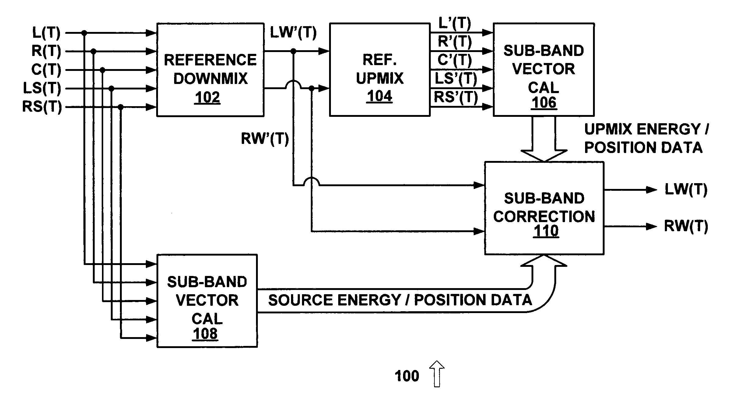
[0026]FIG. 1 is a diagram of a system 100 for dynamic down-mixing from an N-channel audio format to an M-channel audio format with an analysis and correction loop in accordance with an exemplary embodiment of the present invention. System 100 uses 5.1 channel sound (i.e. N=5) and converts the 5.1 channel sound to stereo sound (i.e. M=2), but other suitable numbers of input and output channels can also or alternatively be used.

[0027] The dynamic down-mix process of system 100 is implemented using reference down-mix 102, reference up-mix 104, sub-band vector calculation systems 106 and 108, and sub-band correction system 110. The analysis and correction l...


PUM


Abstract

An audio spatial environment engine is provided for converting from an N channel audio system to an M channel audio system, such as in a dynamic down-mixer where N and M are integers and N is greater than M. The dynamic down-mix methodology consists of a static down-mix system utilizing an intelligent analysis and correction loop. The original N-channel audio signals are provided to a static down-mix process which produces a down-mixed M-channel audio signal. That M-channel audio signal is provided to an up-mix process which generates a subsequent N-channel audio signal. Any spectral, temporal, or spatial inaccuracies between the original N-channel audio and the subsequent up-mixed N-channel audio are then identified and corrected in the down-mixed M-channel audio signal over a plurality of frequency bands generating the final down-mixed M-channel audio signal. The corrections performed on the down-mixed M-channel audio signal consist of modifications to the relevant inter-channel spatial cues such as inter-channel level difference (ICLD) and inter-channel coherence (ICC) per frequency band.

Description

RELATED APPLICATIONS [0001] This application claims priority to U.S. provisional application 60 / 622,922, filed Oct. 28, 2004, entitled “2-to-N Rendering;” U.S. patent application Ser. No. 10 / 975,841, filed Oct. 28, 2004, entitled “Audio Spatial Environment Engine;” U.S. patent application Ser. No. ______ (attorney docket number 13646.0012), “Audio Spatial Environment Up-Mixer,” filed herewith; and U.S. patent application Ser. No. ______ (attorney docket number 13646.0010), “Audio Spatial Environment Engine,” filed herewith, each of which are commonly owned and which are hereby incorporated by reference for all purposes.FIELD OF THE INVENTION [0002] The present invention pertains to the field of audio data processing, and more particularly to a system and method for down-mixing from N-channel data to M-channel data, where N and M are integers and N is greater than M. BACKGROUND OF THE INVENTION [0003] Systems and methods for processing audio data are known in the art. Most of these s...

Claims


Application Information

Patent Timeline
Patent Type & Authority Applications(United States)
IPC IPC(8): G10L21/00
CPCG10L19/008
Inventor THOMPSON, JEFFREY K.REAMS, ROBERT W.WARNER, AARON
Owner DTS
Learn More