Terminal-mounting seat

a technology of mounting brackets and seat posts, applied in the direction of coupling contact members, coupling device connections, contact members penetrating/cutting insulation/cable strands, etc., can solve problems such as electric shock

Active Publication Date: 2006-05-18
EXCEL CELL ELECTRONICS
View PDF13 Cites 28 Cited by
  • Summary
  • Abstract
  • Description
  • Claims
  • Application Information

AI Technical Summary

Benefits of technology

[0008] Therefore, the object of the present invention is to provide a terminal-mounting seat that can eliminate the aforesaid drawbacks of the prior art.

Problems solved by technology

Exposure of the contacting end portion 133 easily results in electrical shock as this increase, the likelihood that a user will inadvertently contact the same.

Method used


Image

  • Terminal-mounting seat
  • Terminal-mounting seat
  • Terminal-mounting seat

Examples


Embodiment Construction

[0022] Before the present invention is described in greater detail, it should be noted that like elements are denoted by the same reference numerals throughout the disclosure.

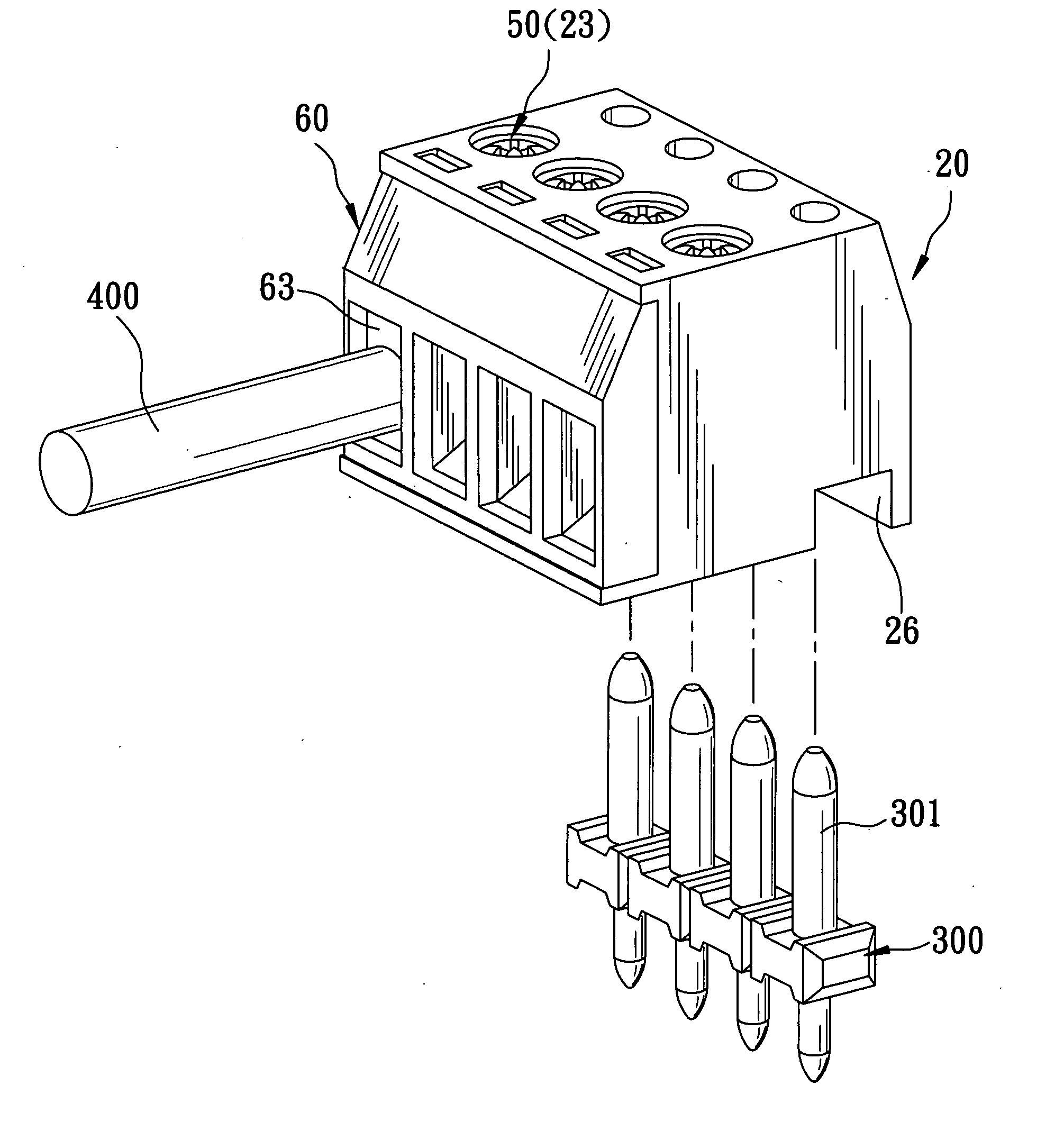
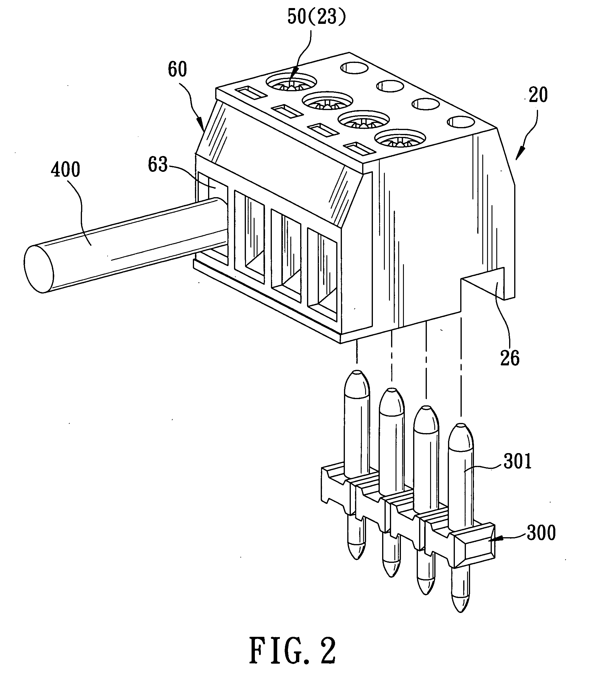
[0023] Referring to FIGS. 2, 3 and 4, the preferred embodiment of a terminal-mounting seat according to the present invention is shown to include a housing 20, a plurality of conducting members 40, a plurality of mounting blocks 30, a cover body 60, and a plurality of fastening members 50. It is noted that only one conducting member 40, the corresponding mounting block 30 and the corresponding fastening member 50 are shown in FIG. 3.

[0024] The housing 20 has a front open side 24, a rear side 27, and opposite top and bottom walls 28, 29. In this embodiment, the housing 20 further has a plurality of parallel partition walls 21 disposed vertically and connected between the top and bottom walls 28, 29 such that the top and bottom walls 28, 29, and the partition walls 21 confine a plurality of receiving spaces 22....


PUM


Abstract

A terminal-mounting seat includes a conducting member mounted fixedly in a housing and having an elongate contacting end portion and a terminal-engaging end portion that is in electrical contact with a terminal and that is adjacent to a front open side of the housing. A mounting block is mounted movably in the housing, and has an insert hole permitting extension of the contacting end portion thereinto. A cover body is mounted on the front open side of the housing for concealing the conducting member and the mounting block within the housing, and has an insert groove permitting insertion of an electrical wire therethrough via the front open side. A fastening member is mounted rotatably in a through hole in the housing, engages a threaded hole in the mounting block, and is operable so as to move the mounting block to move upwardly within the housing.

Description

BACKGROUND OF THE INVENTION [0001] 1. Field of the Invention [0002] The invention relates to a terminal-mounting seat, more particularly to a terminal-mounting seat that can prevent electrical shock during use, and that can ensure electrical connection between a terminal and an electrical wire. [0003] 2. Description of the Related Art [0004] Referring to FIG. 1, a conventional terminal-mounting seat 10 is shown to include a housing 11, a mounting block 12, a conducting member 13, and a fastening member 14. The housing 11 is configured with a receiving space 111, and has a front open side 112, and opposite top and bottom walls 113, 114. The top wall 113 is formed with a through hole 1131 in spatial communication with the receiving space 111. The bottom wall 114 is formed with a counterbore 1141 that is in spatial communication with the receiving space 111 and that permits extension of a terminal 100 therethrough. The conducting member 13 is mounted fixedly in the receiving space 111 ...

Claims


Application Information

Patent Timeline
Patent Type & Authority Applications(United States)
IPC IPC(8): H01R9/22H01R4/24H01R4/36H01R9/24H01R11/05H01R13/11
CPCH01R4/363H01R9/223H01R9/2491H01R11/05H01R13/111H01R12/515
Inventor CHIANG, CHING-CHUNG
Owner EXCEL CELL ELECTRONICS
Why Eureka
Try Eureka