DC/DC converter
a dc/dc converter and converter technology, applied in the field of dc/dc converters, can solve the problems of reducing the operation efficiency and the weight core has been a significant hindrance to the reduction of so as to reduce the overall size and weight of the dc/dc converter, reduce the size and weight of the coil section, and simplify the construction of the dc/dc converter.
- Summary
- Abstract
- Description
- Claims
- Application Information
AI Technical Summary
Benefits of technology
Problems solved by technology
Method used
Image
Examples
first embodiment
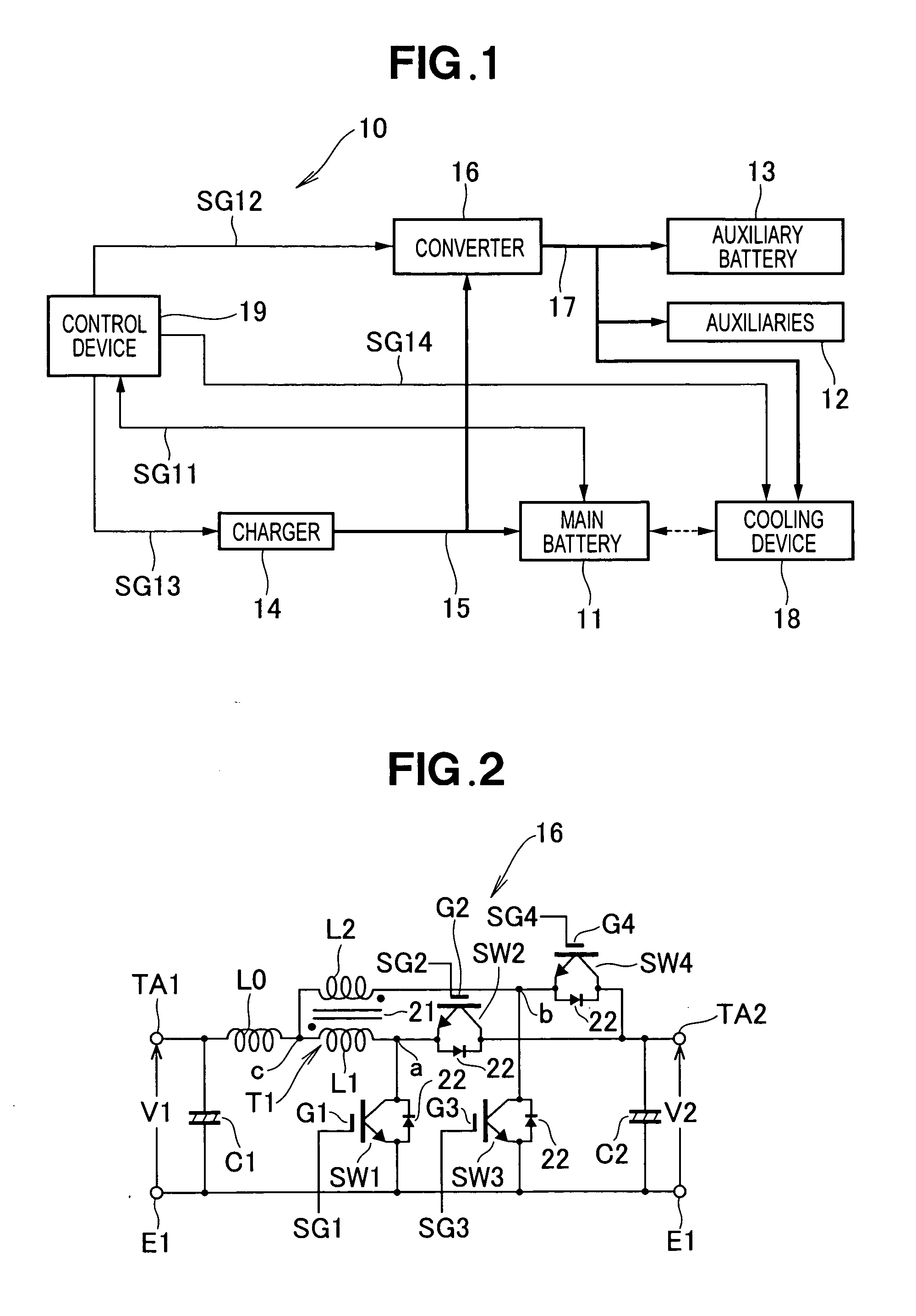
[0089] Similarly to the first embodiment, the DC / DC converter 31 includes a smoothing capacitor C1, an inductor (coil) L0, a transformer T1, four switching elements SW1, SW2, SW3 and SW4 and a smoothing capacitor C2. The DC / DC converter 31 also includes two diodes 32 and 33. DC voltage V1 is input to a positive-pole terminal TA1 of the low-voltage-side input port, and a DC voltage V2 is output from a positive-pole terminal TA2 of the high-voltage-side output port. Reference character E1 represents a common reference terminal (ground terminal).
second embodiment
[0090] The transformer T1 includes a core 21, and primary and secondary windings L1 and L2. The primary and secondary windings L1 and L2 are connected with each other and wound in opposite winding directions (i.e., interconnected in an “oppositely-wound configuration”). Winding ratio between the primary winding L1 and the secondary winding L2 is preferably 1:1. In the second embodiment, the primary and secondary windings L1 and L2 include intermediate taps 34 and 35, respectively. As shown in FIG. 16, the intermediate tap 34 divides the primary winding L1 with a winding ratio of n1:n2. With the winding ratio of n1:n2, a voltage-boosting ratio N of the voltage-boosting DC / DC converter 31 can be determined by
N=(n1+n2) / n1+1
The winding division ratio is determined in accordance with voltage-boosting / lowering requirements of a system to which is applied the present invention.
[0091] In the DC / DC converter 31, the inductor L0 is connected at one terminal to the terminal TA1, and a commo...
third embodiment
[0109] the DC / DC converter 41 is constructed to perform voltage-boosting operation. In the voltage-boosting operation, the DC voltage V1 input to the low-voltage-side input port is boosted to the DC voltage V2 at the high-voltage-side input port.
[0110] Similarly to the second embodiment, the DC / DC converter 41 includes a smoothing capacitor C1, an inductor (coil) L0, a transformer T1, two switching elements SW1 and SW3, a smoothing capacitor C2, and two diodes 32 and 33. In the third embodiment, the switching elements SW2 and SW4 employed in the second embodiment are omitted and replaced with diodes 42 and 43. The DC voltage V1 is input to the positive-pole terminal TA1 of the low-voltage-side input port, and the DC voltage V2 (>V1) is output to the positive-pole terminal TA2 of the high-voltage-side output port. Reference character E1 represents a common reference terminal (ground terminal).
[0111] In the DC / DC converter 41, the diode 42 is connected between the intermediate tap 34...
PUM
 Abstract
Description
Claims
Application Information
 - R&D
- Intellectual Property
- Life Sciences
- Materials
- Tech Scout
- Unparalleled Data Quality
- Higher Quality Content
- 60% Fewer Hallucinations
Browse by: Latest US Patents, China's latest patents, Technical Efficacy Thesaurus, Application Domain, Technology Topic, Popular Technical Reports.
© 2025 PatSnap. All rights reserved.Legal|Privacy policy|Modern Slavery Act Transparency Statement|Sitemap|About US| Contact US: help@patsnap.com


