Cyclone-type vacuum cleaner
a vacuum cleaner and cyclone-type technology, applied in the field of vacuum cleaners, can solve the problems of increasing the needed size reducing the effectiveness of the vacuum cleaner, and unpleasant and unsanitary for the user, so as to increase the dust collection capacity and the effect of heightened dust receptacles
- Summary
- Abstract
- Description
- Claims
- Application Information
AI Technical Summary
Benefits of technology
Problems solved by technology
Method used
Image
Examples
first embodiment
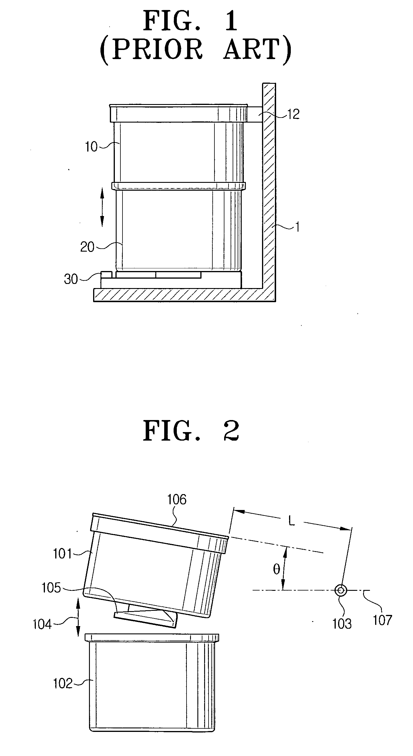
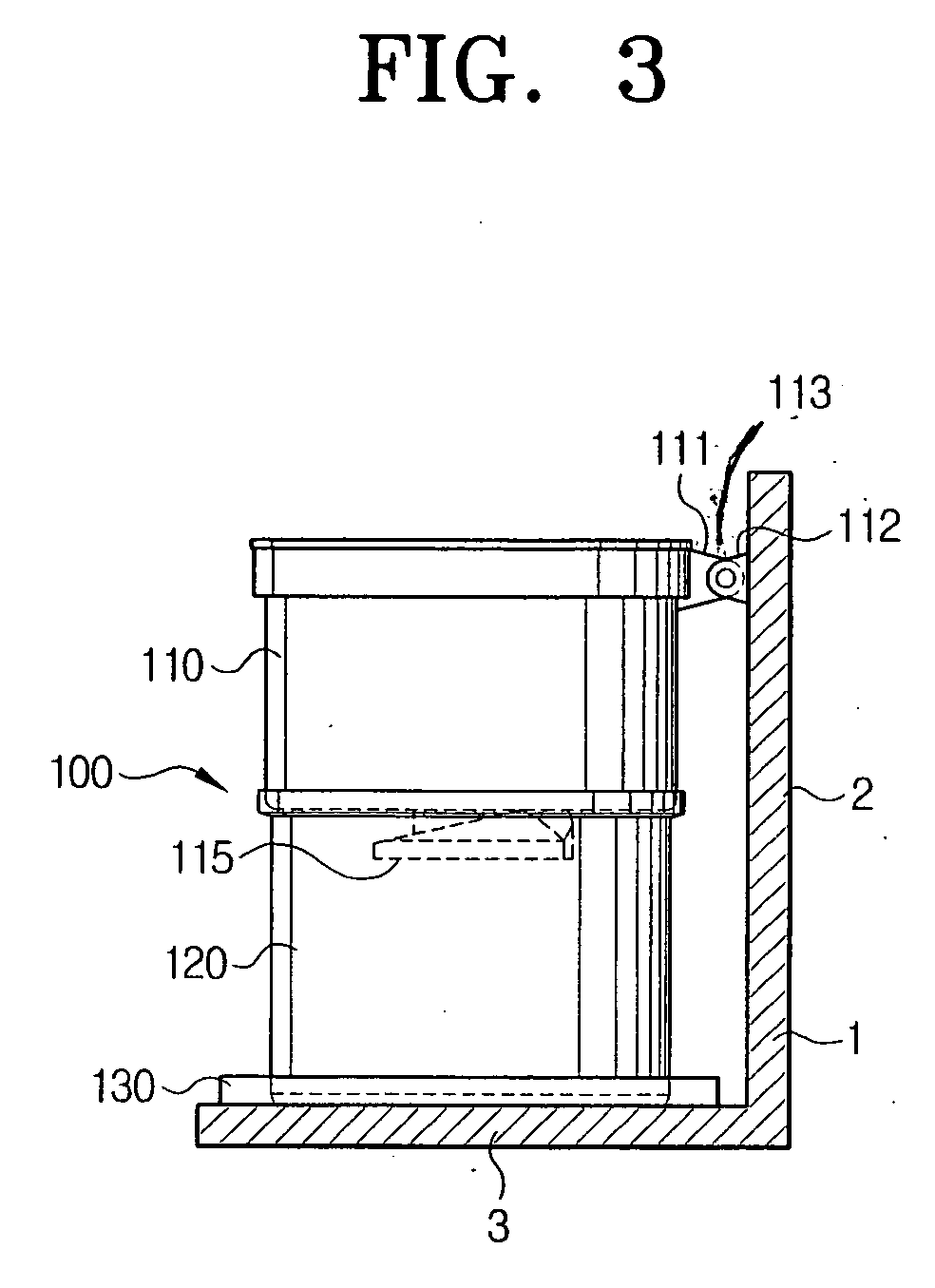
[0032]FIG. 3 shows a cyclone dust collector as mounted to a cleaner body according to the present invention. In this figure, a cyclone dust collector 100 is mounted to a receiving portion in the cleaner body 1 and a vacuum generator (not shown) is disposed at one side of the cyclone dust collector 100. The cyclone dust collector 100 comprises a cyclone body 110 for separating dust from drawn-in air, and a dust receptacle 120 for collecting the dust separated by the cyclone body 110.
[0033] The cyclone body 110 is attached to a partition 2 of the cleaner body 1 by a two-part hinge 113. The partition 2 constitutes the receiving portion of the cleaner body 1.
[0034] As can be seen, the cyclone body 110 is attached to (or in an alternate embodiment comprises) a first part 111 of the hinge 113 that is located (or formed) at one side of the cyclone body 110. A second hinge supporting part 112 of the hinge 113 is attached to (or in an alternate embodiment comprises) part of the partition 2 ...
second embodiment
[0039] For FIG. 5 shows the invention, which provides even greater capacity dust receptacle 120′ and which enables the dust receptacle 120′ to be detached from the cyclone body 110′ at smaller inclination angles of the cyclone body 110′ around the axis of the hinge 113. In FIG. 5, the top opening 127 of the dust receptacle 120′ and the bottom opening 117 of the cyclone body 110′ are canted or inclined with respect to each other as shown. The bottom opening 117 of the cyclone body 110′ of the dust collector 100′ is inclined at an angle that matches the inclination of the top opening 127 of the dust receptacle 120′
[0040] A distinctive feature of the second embodiment shown in FIG. 5 is that the cyclone body 110′ comprises a sloping bottom opening 117 the pitch or inclination of which matches the pitch or inclination of the opening 127 of the dust receptacle 120.′
[0041] The top opening, which is also referred to herein as a first sloping part 127, is slanted “upward” in the direction a...
third embodiment
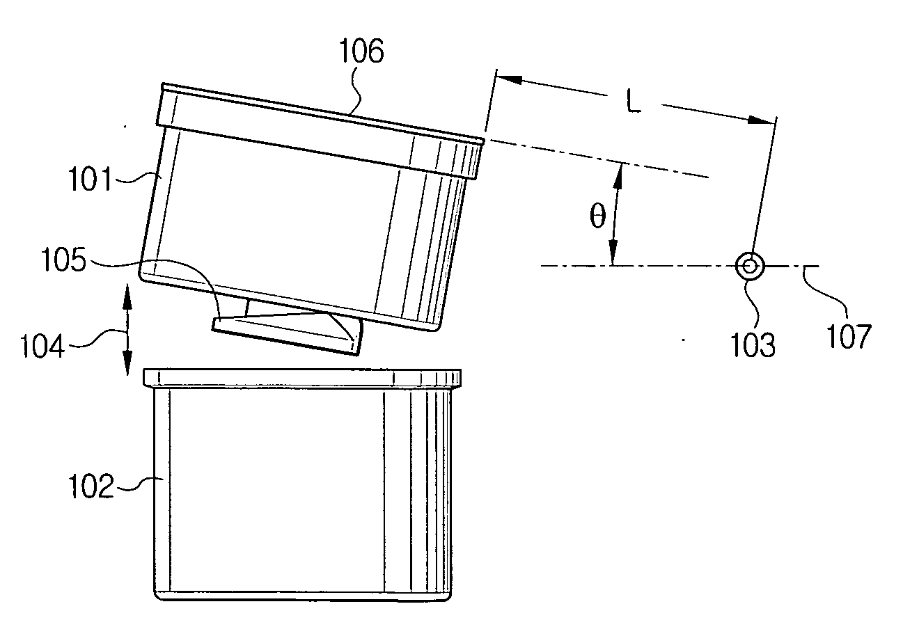
[0045]FIG. 8 shows a cyclone dust collector mounted in a cleaner body of a cyclone vacuum cleaner. With reference to FIG. 8, a cyclone dust collector 100″ comprises a cyclone body 110″ and a dust collector 120″. As shown in FIG. 8, the cyclone body 110″ is mounted to the receiving portion of the cleaner body 1 to separate dust from drawn-in air. A dust receptacle 120″ below the cyclone body 110 collects separated dust.
[0046] As can be seen in FIGS. 8 and 9, the cyclone body 110″ is mounted to a hinged cover 5. The hinged cover 5, being hingedly attached to the cleaner body 1 by a hinge 113″, allows it to pivot or “lift” upwardly by an amount that is proportional to the angle to which the cover is rotated. Therefore, by opening the cover 5 with respect to the cleaner body 1, as shown in FIG. 9, the cyclone body 110″ is separated from the dust receptacle 120″. By closing the cover 5, the cyclone body 110″ is connected to the dust receptacle 120″, as shown in FIG. 8.
[0047] The dust re...
PUM
 Abstract
Description
Claims
Application Information
 - R&D
- Intellectual Property
- Life Sciences
- Materials
- Tech Scout
- Unparalleled Data Quality
- Higher Quality Content
- 60% Fewer Hallucinations
Browse by: Latest US Patents, China's latest patents, Technical Efficacy Thesaurus, Application Domain, Technology Topic, Popular Technical Reports.
© 2025 PatSnap. All rights reserved.Legal|Privacy policy|Modern Slavery Act Transparency Statement|Sitemap|About US| Contact US: help@patsnap.com


