Eureka AIR delivers breakthrough ideas for toughest innovation challenges, trusted by R&D personnel around the world.

Methods of using coiled tubing inspection data

a technology of coiled tubing and inspection data, which is applied in the direction of instruments, surveying, borehole/well accessories, etc., can solve the problems of ballooning (increased outside diameter), significant wall thickness loss, and wall thinning

Active Publication Date: 2006-05-11
SCHLUMBERGER TECH CORP
View PDF11 Cites 28 Cited by
  • Summary
  • Abstract
  • Description
  • Claims
  • Application Information

AI Technical Summary

Benefits of technology

[0009] In accordance with the present invention, methods of using inspection data for coiled tubing are described that reduce or overcome problems in previously known methods.
[0023] (b) using the geometric database in real time to modify parameters of the coiled tubing operation, optionally in conjunction with other real time operation parameters, to predict and anticipate potential operation risks and to use feedback control to reduce or eliminate such operation risks.

Problems solved by technology

For example, acidizing through coiled tubing could cause coiled tubing corrosion, while corrosion could lead to wall thickness loss or pitting on the surface of the coiled tubing; fracturing through coiled tubing could cause erosion on the coiled tubing surface, leading to significant wall thickness loss; high pressure coiled tubing operation could lead to ballooning (increase of outside diameter) and wall thinning; even during normal workover operation, the cross section of coiled tubing will gradually become oval and the length of coiled tubing may gradually grow.
All these changes in coiled tubing geometry (wall thickness, diameter, shape) could compromise the mechanical integrity and the operability of the coiled tubing.
For example, loss of wall thickness could lead to catastrophic failure of tubing parting, while a balloon section of coiled tubing could get stuck or crushed at the injector.
Moreover, for many applications, it is not sufficient to make a single measurement or set of measurements at a single point along the coiled tubing.
The amount of permanent elongation may not be uniform through the entire coiled tubing string.
Hence, knowledge of simple diameter or wall thickness measurements relative to the length of coiled tubing may not be sufficient, especially for a tapered coiled tubing string.

Method used


Image

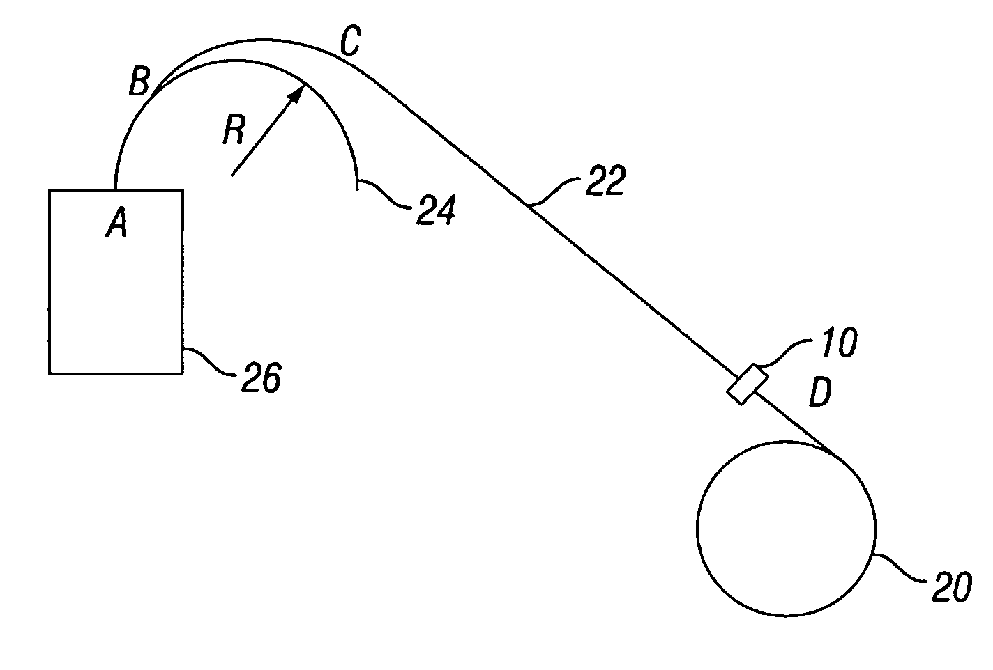
  • Methods of using coiled tubing inspection data
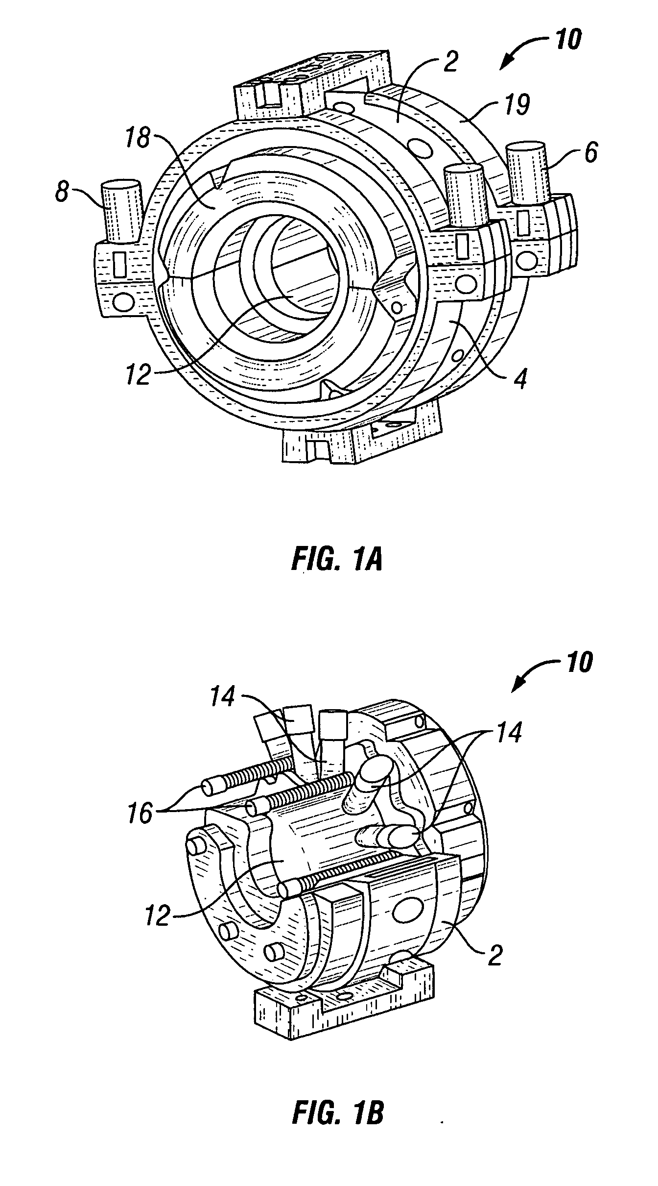
  • Methods of using coiled tubing inspection data
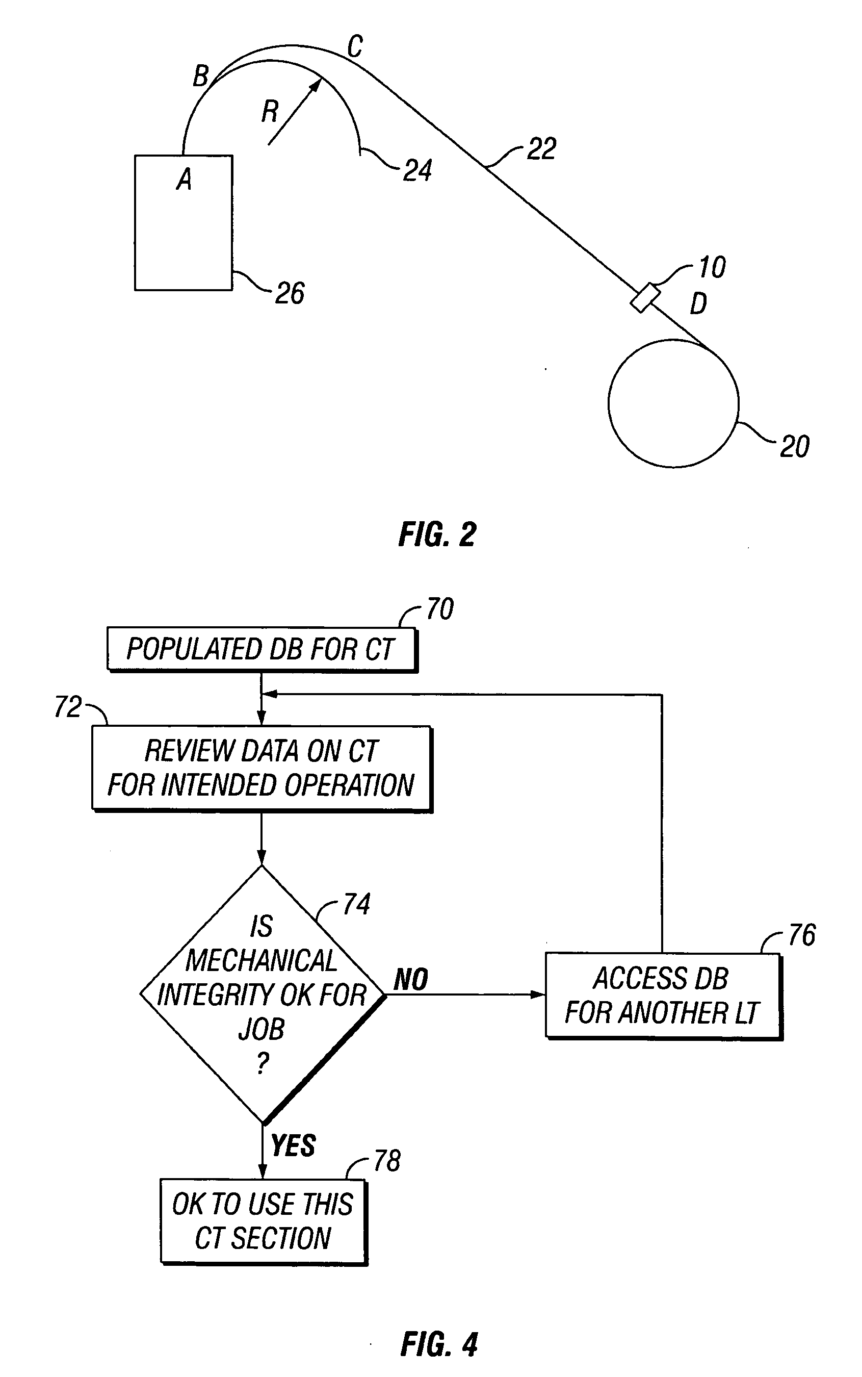
  • Methods of using coiled tubing inspection data

Examples


Embodiment Construction

[0040] In the following description, numerous details are set forth to provide an understanding of the present invention. However, it will be understood by those skilled in the art that the present invention may be practiced without these details and that numerous variations or modifications from the described embodiments may be possible. For example, in the discussion herein, aspects of the inventive methods and apparatus are developed within the general context of inspection of coiled tubing and using the data in real time or near real time, which may employ computer-executable instructions, such as program modules, being executed by one or more conventional computers. Generally, program modules include routines, programs, objects, components, data structures, etc. that perform particular tasks or implement particular abstract data types. Moreover, those skilled in the art will appreciate that the inventive methods and apparatus may be practiced in whole or in part with other comp...


PUM


Abstract

Methods for generating geometric databases of coiled tubing inspection data and using the data in job design, real time monitoring and automated feedback control of operations are described. One method includes creating a grid of spatial positions on a length of coiled tubing as it traverses through an inspection apparatus having a plurality of sensors for detecting defects in the coiled tubing. Real time data may be compared to historical or nominal data for the coiled tubing. Another method includes monitoring, in real time or near real time, the status of tubing dimension (thickness, diameter, ovality, shape) during a coiled tubing operation, such as acidizing, fracturing, high pressure operations, drilling, and wellbore cleanouts. This abstract allows a searcher or other reader to quickly ascertain the subject matter of the disclosure. It will not be used to interpret or limit the scope or meaning of the claims.

Description

[0001] This non-provisional patent application claims priority to provisional application Ser. No. 60 / 625,681 filed Nov. 5, 2004.BACKGROUND OF THE INVENTION [0002] 1. Field of Invention [0003] The present invention relates generally to the field of inspection of ferrous tubular members, and more specifically to inspection of coiled tubing apparatus and methods of using the data from such inspections. [0004] 2. Related Art [0005] Through the service life of a coiled tubing string (during its storage, transportation and workover operations), the mechanical integrity of the coiled tubing, such as tension capacity, fatigue life, burst or collapse pressure resistance, is constantly changing as a result of coiled tubing geometrical changes. For example, acidizing through coiled tubing could cause coiled tubing corrosion, while corrosion could lead to wall thickness loss or pitting on the surface of the coiled tubing; fracturing through coiled tubing could cause erosion on the coiled tubin...

Claims


Application Information

Patent Timeline
IPC IPC(8): E21B47/00
CPCE21B17/20E21B41/00E21B12/02E21B19/00G01B21/12
Inventor ZHENG, SHUNFENGADNAN, SARMADLOVELL, JOHN R.
Owner SCHLUMBERGER TECH CORP
Why Eureka
Eureka Blog
Learn More