Architecture for multiple-antenna systems

a technology of antenna system and architecture, applied in the field of radio frequency receiver and transmitter system having multiple antennas, can solve the problems of increasing power consumption, increasing hardware requirements, and impracticality of implementation

Inactive Publication Date: 2006-05-04
RAFATI HAMID
View PDF3 Cites 16 Cited by
  • Summary
  • Abstract
  • Description
  • Claims
  • Application Information

AI Technical Summary

Benefits of technology

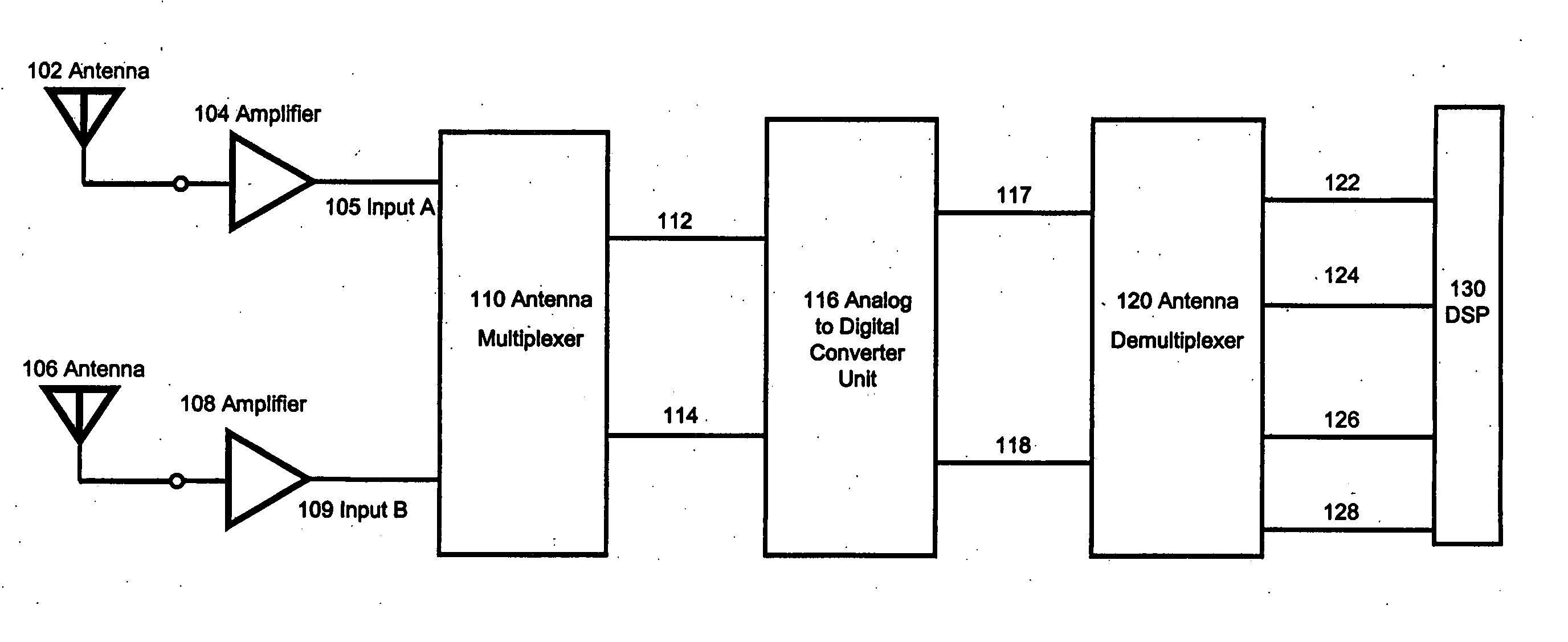
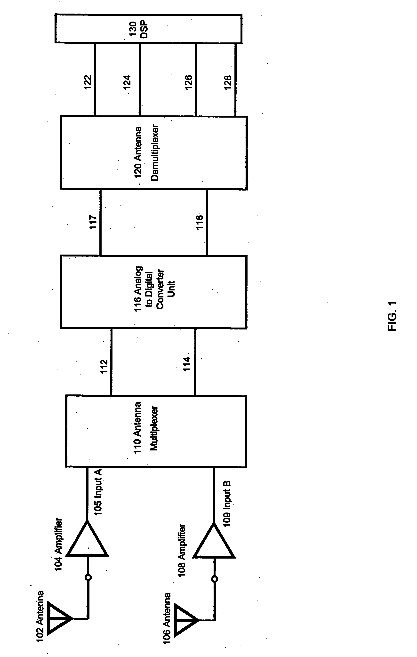
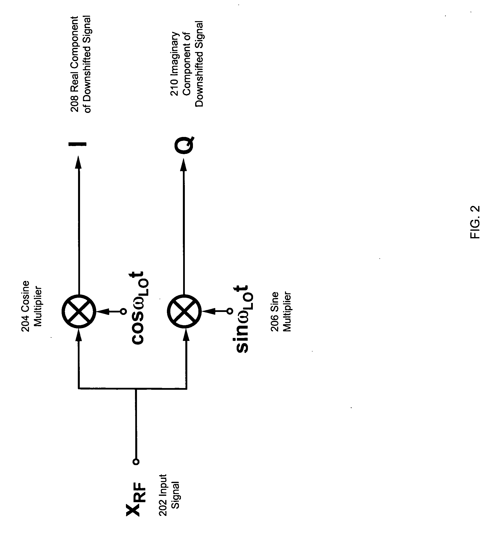
[0011] The invention is a system and method for sharing components of a single-path receiver or transmitter system between multiple antennas without introducing a time-periodic switch. Specifically, according to one embodiment of the present invention, multiple antennas simultaneously share an analog-to-digital converter unit. The signal from one antenna is downconverted to a positive frequency band while the signal from another antenna is downconverted to a negative frequency band, allowing the signals to be processed by the analog-to-digital converter unit with minimal interference between signals and without the need for time-periodic switching.
[0012] According to another embodiment of the present invention, multiple antenna transmitters share a digital-to-analog converter unit. The signal from one antenna is upconverted to a positive frequency band while the signal from another antenna is upconverted to a negative frequency band, allowing the signals to be processed by the digital-to-analog converter unit with minimal interference between signals and without the need for time-periodic switching.
[0013] As the analog-to-digital, and digital-to-analog converters units make up a significant portion of the size, cost, and power of a typical single-path receiver and transmitter, the advantages of reducing the number of analog-to-digital, and digital-to-analog converter units in a multiple-antenna receiver and transmitter system are significant.

Problems solved by technology

However, there are several requirements for multiple-antenna systems that have so far made implementation impractical.
However, such an approach greatly increases power consumption and substantially increases the hardware required when compared to a single-antenna receiver system.
Cost, size, and power constraints frequently render this method impractical.
However, the switching step introduces several problems.
For any switching rate, there is always an interfering signal that could corrupt the desired signal as a result of switching.
Also, due to latency of the filters required in a receiver, artifacts of one antenna's signal remain in the receive-path for some time after the switch to another antenna has occurred, resulting in interference between the signals from various antennas.
Switching between the signals from various antennas results in corruptions and interferences that impair the overall performance of the receiver system.
Similar challenges regarding cost, power, size, and interference exist in implementing multiple-antenna transmitter systems.

Method used


Image

  • Architecture for multiple-antenna systems
  • Architecture for multiple-antenna systems
  • Architecture for multiple-antenna systems

Examples


Embodiment Construction

[0024] A preferred embodiment of the present invention is now described with reference to the figures where like reference numbers indicate identical or functionally similar elements. Also in the figures, the left most digits of each reference number corresponds to the figure in which the reference number is first used.

[0025] Reference in the specification to “one embodiment” or to “an embodiment” means that a particular feature, structure, or characteristic described in connection with the embodiments is included in at least one embodiment of the invention. The appearances of the phrase “in one embodiment” in various places in the specification are not necessarily all referring to the same embodiment.

[0026] Some portions of the detailed description that follows are presented in terms of algorithms and symbolic representations of operations on data bits within a computer memory. These algorithmic descriptions and representations are the means used by those skilled in the data proc...


PUM


Abstract

The invention is a system and method for sharing components of a single-path receiver or transmitter system multiple antennas. Specifically, according to one embodiment of the present invention, multiple antennas simultaneously share an analog-to-digital converter unit. The signal from one antenna is downconverted to a positive frequency band while the signal from another antenna is downconverted to a negative frequency band, allowing the signals to be processed by the analog-to-digital converter unit with minimal interference between signals and without the need for time-periodic switching. According to another embodiment of the present invention, multiple antennas simultaneously share a digital-to-analog converter unit.

Description

RELATED APPLICATIONS [0001] This application claims benefit from U.S. provisional application No. 60 / 625,410 and from U.S. provisional application No. 60 / 688,868, which are incorporated by reference herein in their entirety.FIELD OF THE INVENTION [0002] The invention relates generally to radio frequency receiver and transmitter systems, and, specifically, to radio frequency receiver and transmitter systems having multiple antennas. BACKGROUND OF THE INVENTION [0003] The use of multiple antennas and receivers can substantially boost the performance of wireless communication systems. For example, antenna diversity and beamforming techniques improve the link budget considerably. Moreover, multiple-input multiple-output (MIMO) systems can raise the channel capacity in the presence of multipath fading. The performance of wireless communication systems could be improved if there existed an efficient way to implement receivers and transmitters using multiple antennas. However, there are se...

Claims


Application Information

Patent Timeline
Patent Type & Authority Applications(United States)
IPC IPC(8): H04B17/02H04B1/06H04B17/40
CPCH04B7/0845H04B7/0848
Inventor RAFATI, HAMID
Owner RAFATI HAMID
Why Eureka
Try Eureka