Optical projection apparatus

Inactive Publication Date: 2006-05-04
YOUNG OPTICS
View PDF12 Cites 5 Cited by
  • Summary
  • Abstract
  • Description
  • Claims
  • Application Information

AI Technical Summary

Benefits of technology

[0011] One objective of the present invention is to provide an optical projection apparatus using two beam breakers so as to project a darker image with higher contrast and more uniformity.
[0012] Another objective of the present invention is to provide an optical projection apparatus having a light source with multiple output powers so as to project a darker image with higher contrast and more uniformity.
[0013] Still another objective of the present invention is to provide an optical projection apparatus using a light attenuator so as to project a darker image with higher contrast and more uniformity.

Problems solved by technology

Therefore, it is an important issue to increase the image quality of the projection apparatus so as to increase the competitiveness of the product.
However, since the beam breaker 140 only blocks one side of the light beam 120a, it causes the defect that one side of the projected image is darker, while the other side is brighter.
As a result, it cannot effectively increase the contrast of the darker image.

Method used


Image

  • Optical projection apparatus
  • Optical projection apparatus
  • Optical projection apparatus

Examples


Embodiment Construction

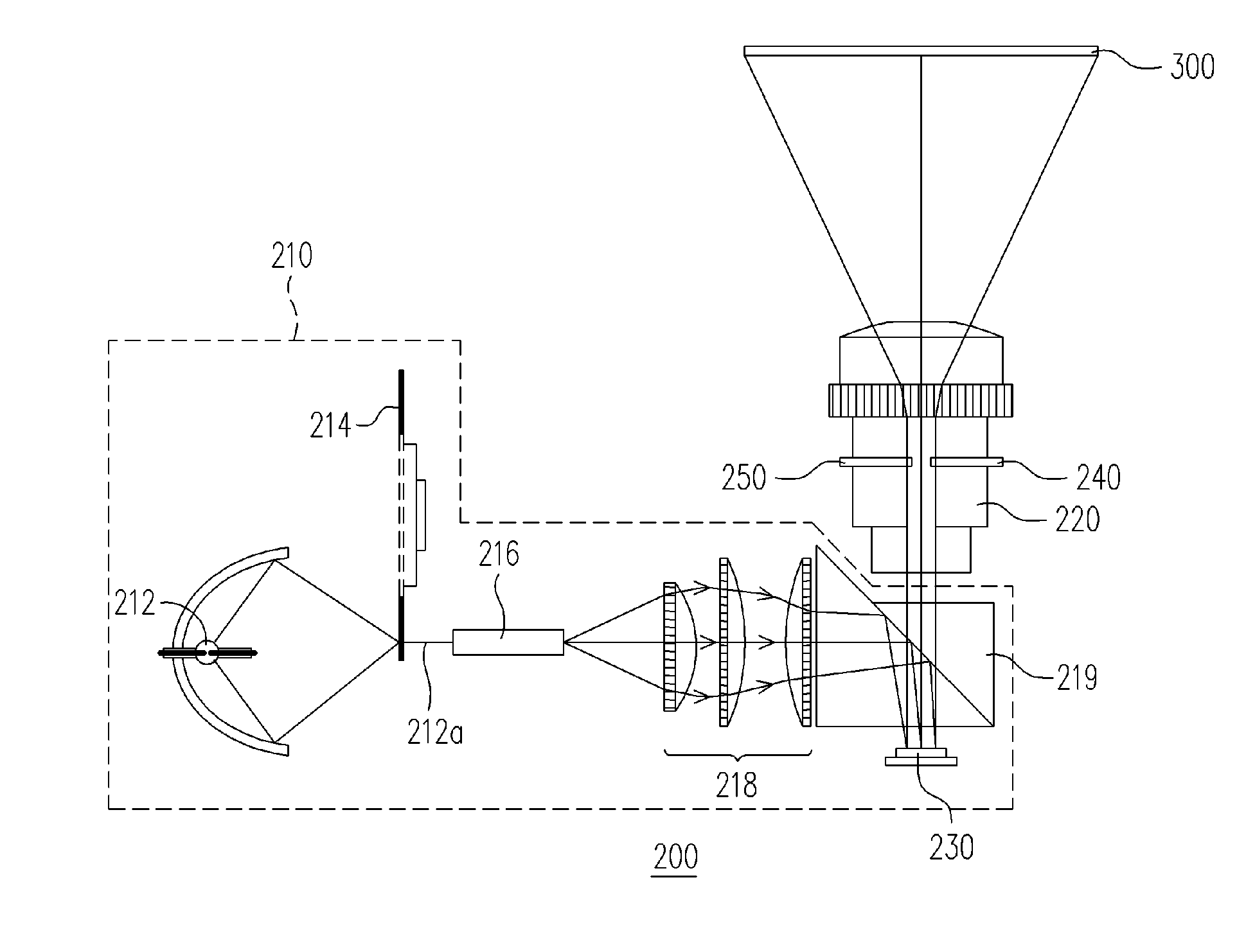
[0030] In FIG. 3, an optical projection apparatus 200 in one embodiment of the present invention includes an illumination system 210, a projection lens unit 220, a reflective light valve 230 and two beam breakers 240 and 250. Wherein, the illumination system 210 has a light source 212 capable of providing a light beam 212a. The projection lens unit 220 and reflective light valve 230 are disposed on the transmission path of the light beam 212a, and the reflective light valve 230 is located between the illumination system 210 and the projection lens unit 220. In addition, the two beam breakers 240 and 250 are disposed in the projection lens unit 220, and the two beam breakers 240 and 250 can cut into the transmission path of the light beam 212a so as to respectively block a portion of the light beam 212a and allow the other portion of the light beam 212a to pass.

[0031] In the foregoing optical projection apparatus 200, the light beam 212a provided from the light source 212 sequential...


PUM


Abstract

An optical projection apparatus includes an illumination system, a projection lens unit, a reflective light valve, a first beam breaker and a second beam breaker. A light beam is provided by the illumination system. The projection lens unit and the reflective light valve are disposed on the transmission path of the light beam, and the reflective light valve is disposed between the illumination system and the projection lens unit. The first beam breaker and the second beam breaker are used to cut into the transmission path of the light beam from different directions to block a part of the light beam, and part of the light beam passes through the first beam breaker and the second beam breaker. The darker image projected by the optical projection apparatus has higher contrast and better uniformity.

Description

CROSS-REFERENCE TO RELATED APPLICATION [0001] This application claims the priority benefit of Taiwan application serial no. 93133307, filed on Nov. 2, 2004. All disclosure of the Taiwan application is incorporated herein by reference. BACKGROUND OF THE INVENTION [0002] 1. Field of Invention [0003] The present invention relates to an optical projection apparatus. More particularly, the present invention relates to an optical projection apparatus, which can project a darker image with higher contrast and better uniformity. [0004] 2. Description of Related Art [0005] In recent years, the projection apparatus of cathode ray tube (CRT) with large volume and weight has been gradually replaced by the liquid crystal display projection apparatus and the digital light processing (DLP) projection apparatus. These products have the properties of being light and portable, and can be directly connected to digital products and project images for display. Under the situation that the manufacturers ...

Claims


Application Information

Patent Timeline
IPC IPC(8): G03B21/14
CPCG03B21/14G03B21/005G03B21/142G03B21/208G03B21/28
Inventor LIAO, CHIA-CHENCHANG, WEI-SHENGCHENG, CHU-MINGCHUANG, KENG-HANLIAO, LOUG-SHENGYANG, SHENG-CHIEHWANG, HSIN-JEN
Owner YOUNG OPTICS
Why Eureka
Try Eureka