Eureka AIR delivers breakthrough ideas for toughest innovation challenges, trusted by R&D personnel around the world.

Plasma reaction chamber with a built-in magnetic core

a technology of plasma reaction chamber and magnetic core, which is applied in the field of plasma reaction chamber, can solve the problems of increasing the cost of extension of factory installation, increasing the cost of consumer, and reducing the facility components of the plasma reaction chamber, so as to improve the productivity per unit area

Inactive Publication Date: 2006-05-04
NEW POWER PLASMA CO LTD
View PDF9 Cites 1 Cited by
  • Summary
  • Abstract
  • Description
  • Claims
  • Application Information

AI Technical Summary

Benefits of technology

The present invention provides a plasma reaction chamber with multiple vacuum chambers integrated in a single chamber housing. The chambers use a common parts system and have inner connection passages for connecting them. A magnetic core is installed in the chamber housing to transfer induced electromotive force to a continuous discharge path formed by the vacuum chambers. Gas can be input and output from the chambers through separate ports. The invention allows for the treatment of substrates in parallel, improving productivity per unit area. A substrate treatment system including the plasma reaction chamber and other components is also provided.

Problems solved by technology

However, increasing the production facilities causes increased cost not only for extension of factory installations but also for space for additional facilities such as a clean room, thereby increasing the expense for the consumer.
However, since each plasma reaction chamber has an independent configuration, decrease in facility components of the plasma reaction chamber and reduction in costs might be not so effective.

Method used


Image

  • Plasma reaction chamber with a built-in magnetic core
  • Plasma reaction chamber with a built-in magnetic core
  • Plasma reaction chamber with a built-in magnetic core

Examples


Embodiment Construction

[0037] Hereinafter, a preferred embodiment of the present invention will be described in more detail referring to the drawings. The embodiment of the present invention may be modified in various ways, and the scope of the invention should be not interpreted as being limited in the following embodiment. The embodiment is proposed for a better understanding by those of ordinary skill in the art. Thus, in the drawings, the shape of each component may be exaggerated in order to emphasize its function for a clearer explanation.

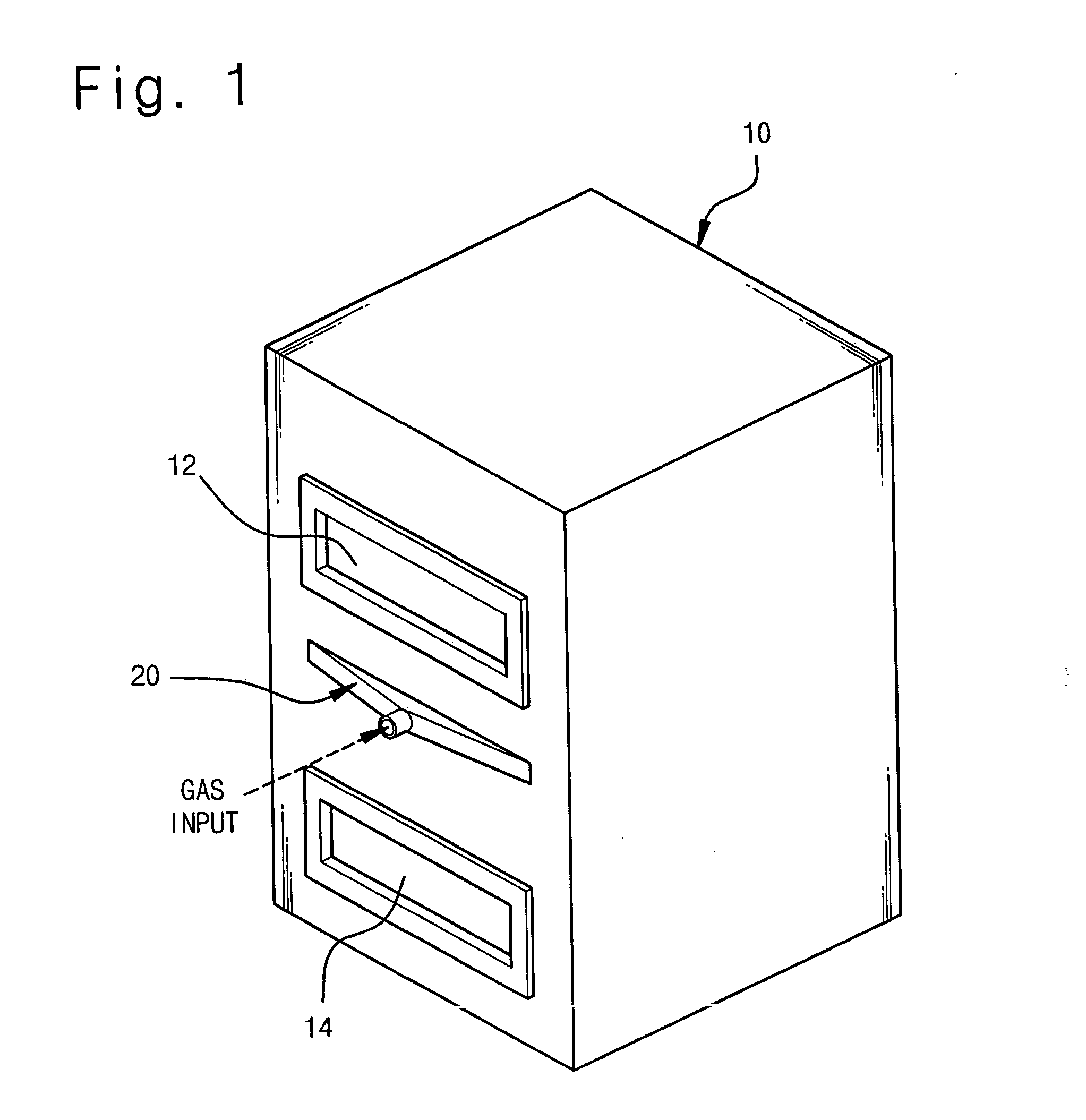
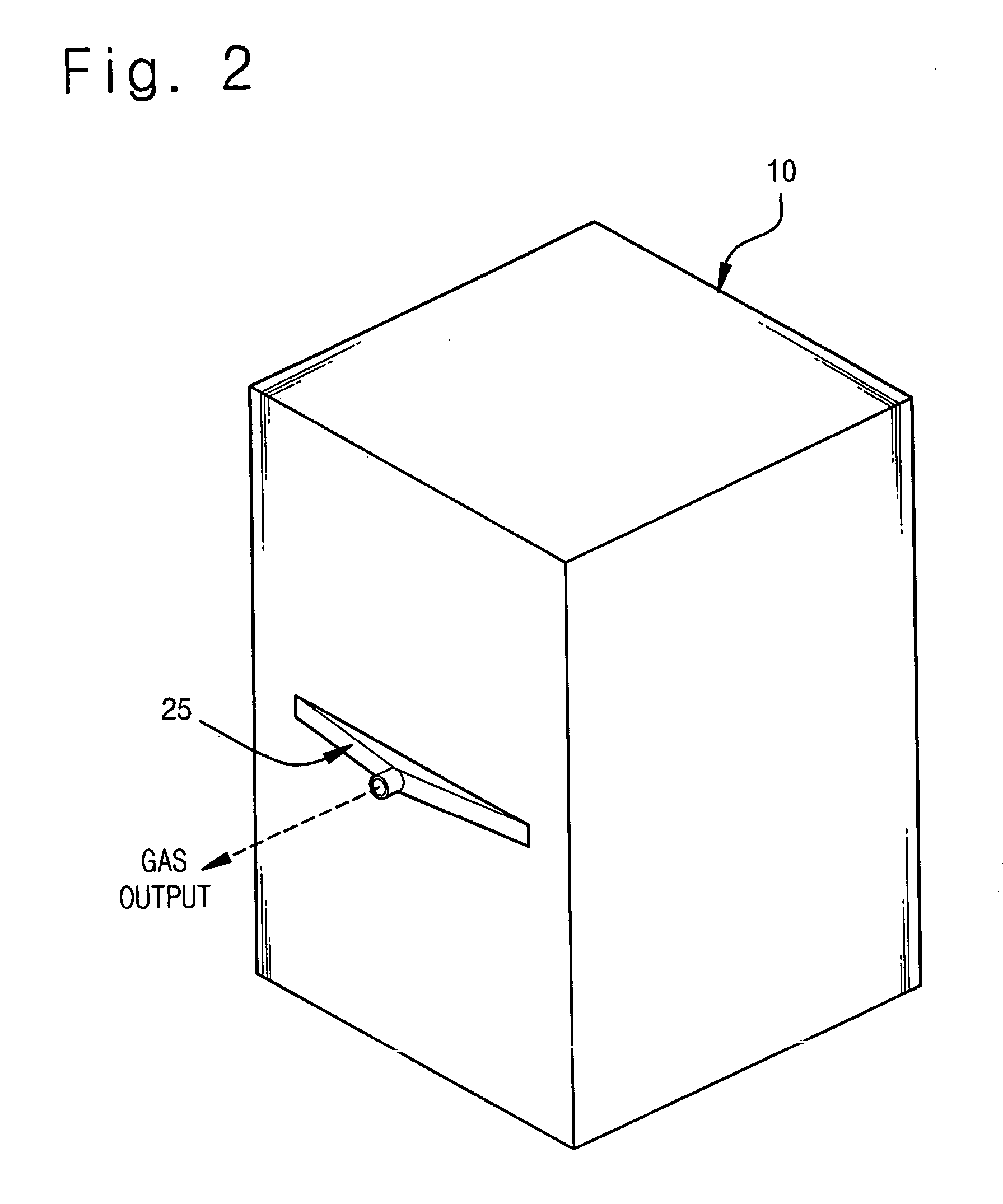
[0038]FIGS. 1 and 2 are perspective views showing front and rear sides of a plasma reaction chamber according to the preferred embodiment of the present invention.

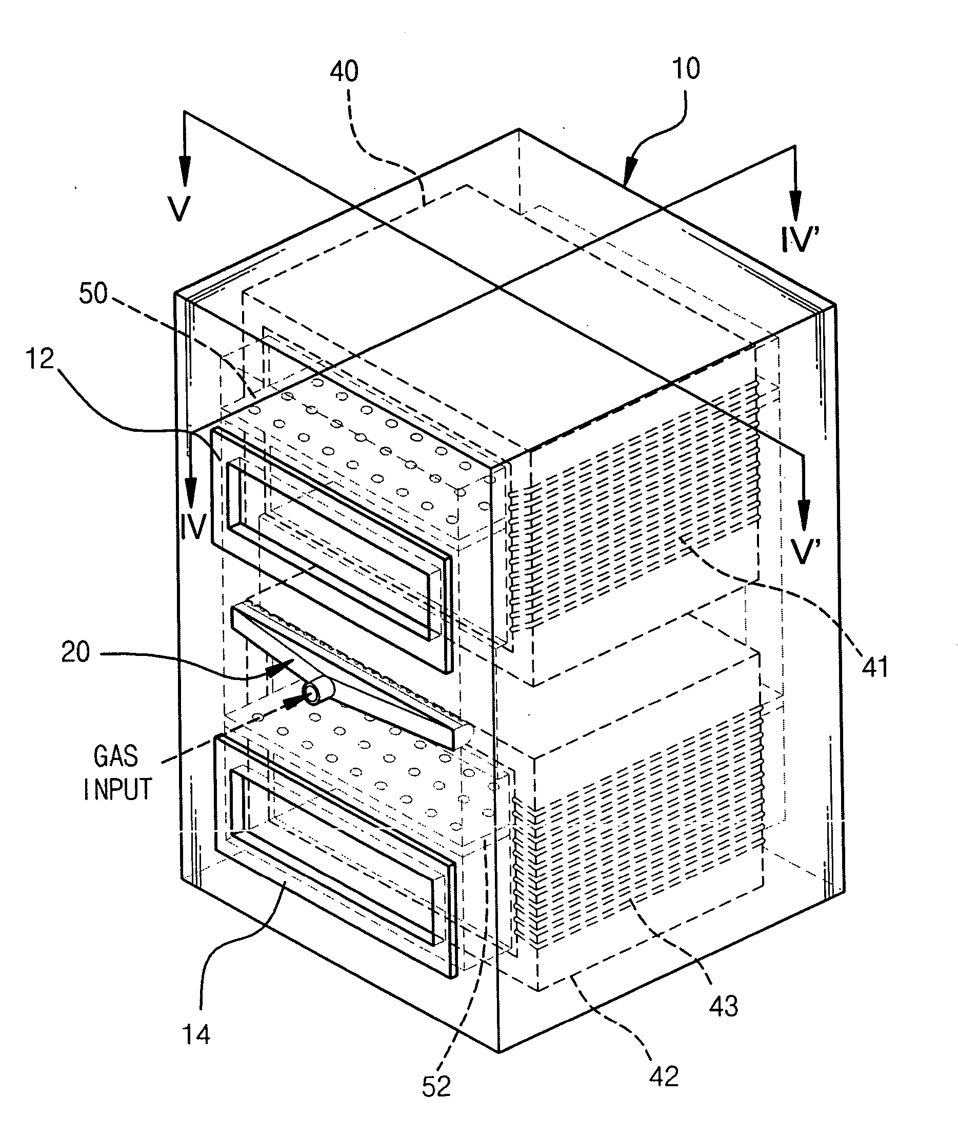
[0039] Referring to FIGS. 1 and 2, the plasma reaction chamber according to this embodiment includes a chamber housing 10 configured so that two vacuum chambers are laminated vertically therein. Two slit valves 12 and 14 for loading or unloading a substrate to be treated in / from the vacuum chamber are a...


PUM

PropertyMeasurementUnit
electromotive forceaaaaaaaaaa
magneticaaaaaaaaaa
vacuumaaaaaaaaaa

Abstract

A plasma reaction chamber includes a chamber housing having two inner connection passages for connecting two vacuum chambers to other vacuum chambers. Two vacuum chambers and two inner connection passages form a continuous discharge path. At least one magnetic core is mounted in two vacuum chambers or two inner connection passages, and a coil connected to a power source is wounded around the magnetic core so as to transfer induced electromotive force to the continuous discharge path. The plasma reaction chamber is configured so that at least two vacuum chambers are integrated in a multiple arrangement, and common parts are shared in common, so that at least two substrates may be treated in parallel at the same time, thereby improving productivity per unit area and making it possible to construct a low-cost and high-efficient substrate treatment system.

Description

CLAIM OF PRIORITY [0001] This application makes reference to, incorporates the same herein, and claims all benefits accruing under 35 U.S.C. § 119 from an application entitled PLASMA REACTION CHAMBER WITH A BUILT-INMAGNETIC CORE filed with the Korean Intellectual Property Office on 3 Nov. 2004, and there duly assigned Serial No. 2004-88816. BACKGROUND OF THE INVENTION [0002] 1. Field of the Invention [0003] The present invention relates to a plasma reaction chamber, and particularly to a plasma reaction chamber having at least two vacuum chambers integrated and disposed in a multiple arrangement so as to treat at least two substrates in parallel. More particularly, the present invention relates to a plasma reaction chamber having a magnetic core built into the plasma reaction chamber so as to generate plasma and provide it to at least two vacuum chambers at the same time. [0004] 2. Description of the Prior Art [0005] As in other industries, various endeavors to improve productivity ...

Claims


Application Information

Patent Timeline
Patent Type & Authority Applications(United States)
IPC IPC(8): C23C16/00
CPCC23C16/45578C23C16/4586C23C16/5096C23C16/54H01J37/32458H01J37/3266H05H1/26
Inventor CHOI, DAE-KYU
Owner NEW POWER PLASMA CO LTD
Why Eureka
Eureka Blog
Learn More