
Substrate-to-mask alignment and securing system with temperature control for use in an automated shadow mask vacuum deposition process

a vacuum deposition and vacuum deposition technology, applied in vacuum evaporation coatings, chemical vapor deposition coatings, coatings, etc., can solve the problems of low vacuum deposition efficiency, and high labor intensity of the process

Inactive Publication Date: 2006-04-27
ADVANTECH GLOBAL LTD
View PDF23 Cites 60 Cited by
  • Summary
  • Abstract
  • Description
  • Claims
  • Application Information

AI Technical Summary

Benefits of technology

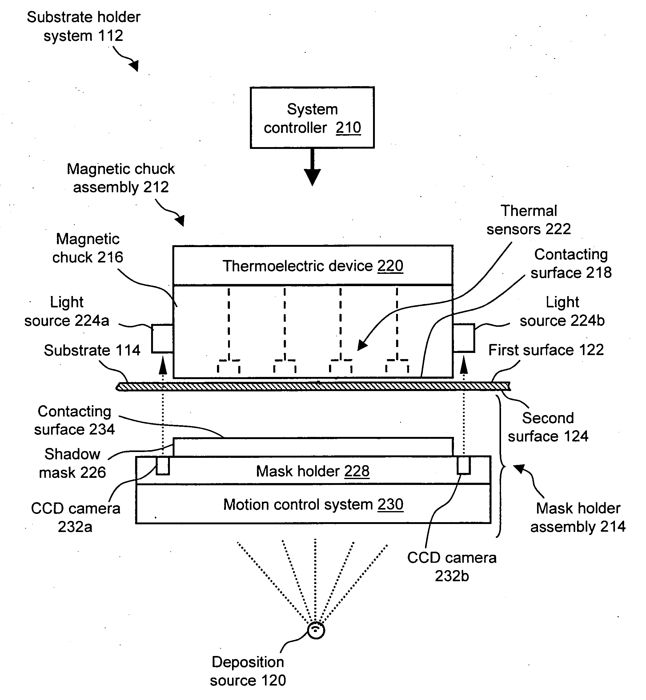
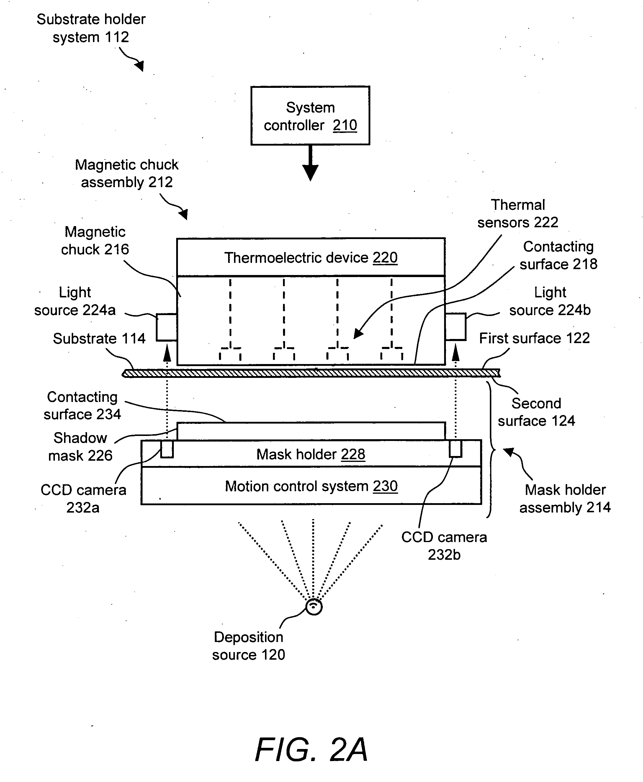
[0021] The system can include a material deposition source operative for depositing a material on the substrate via one or more apertures in the shadow mask. The magnetic chuck, the shadow mask, the substrate and the material deposition source can be positioned in a vacuum vessel. The material deposition source can deposit the material on the substrate in the presence of a vacuum in the vacuum vessel.
[0022] A temperature sensor can sense a temperature of the magnetic chuck and/or the shadow mask and can output a temperature signal corresponding to the sensed temperature. A temperature control device can control the temperature of the magnetic chuck and/or the shadow mask as a function of the temperature signal output by the temperature sensor.
[0023] A mask holder can support the shadow mask and a motion control system can support the mask holder and the shadow mask. The motion control system can be ope...

Problems solved by technology

One of the challenges encountered in the manufacture of such display panels is the development of improved processes that pattern the thin-film electrode structures while they are in an in-line deposition system.
A disadvantage of this process includes its numerous labor intensive steps, each of which is subject to failure or possible contamination of the thin-film device.
Shadow masking is a relatively slow process and usually requires breaking vacuum in the deposition chamber which may result in some thin-film contamination.
For example, non-uniform expansion may cause the mask to be non-planar.
Any such non-uniformity caused by expansion increases the possibility for inaccuracies in the deposition process.

Method used


Image

  • Substrate-to-mask alignment and securing system with temperature control for use in an automated shadow mask vacuum deposition process
  • Substrate-to-mask alignment and securing system with temperature control for use in an automated shadow mask vacuum deposition process
  • Substrate-to-mask alignment and securing system with temperature control for use in an automated shadow mask vacuum deposition process

Examples


Embodiment Construction

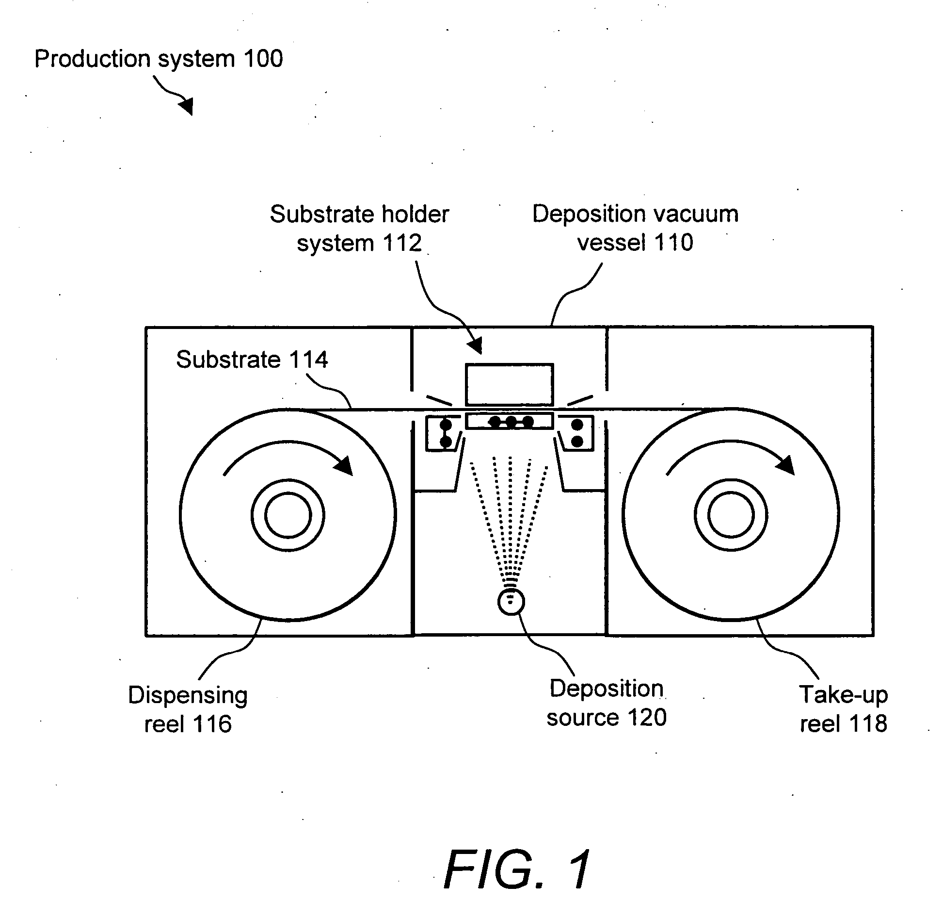
[0030] With reference to FIG. 1, a production system 100 for performing shadow mask vacuum deposition includes a deposition vacuum vessel 110 having therein a substrate holder system 112 for securing a substrate 114 during a deposition operation. Substrate 114 is formed of, for example, anodized aluminum, flexible steel foil, glass or plastic. Physical reference features are formed on substrate 114 in the form of, for example, punched holes or deposited patterns. These physical reference features are used to properly align substrate 114 to substrate holder system 112. Substrate 114 translates through deposition vacuum vessel 110 by way of a reel-to-reel mechanism that includes a dispensing reel 116 and a take-up reel 118.

[0031] Deposition vacuum vessel 110 further includes at least one deposition source 120 which can supply deposition source material, such as metal, semiconductor, insulator, or organic electroluminescent material, to be deposited via an evaporation process.

[0032] ...


PUM

PropertyMeasurementUnit
Temperatureaaaaaaaaaa
Electrical conductoraaaaaaaaaa
Magnetic fluxaaaaaaaaaa

Abstract

The present invention is a substrate holder system for and method of providing a substrate-to-mask alignment mechanism, securing mechanism and temperature control mechanism. The substrate holder system is suitable for use in an automated shadow mask vacuum deposition process. The substrate holder system includes a system controller, and a substrate arranged between a magnetic chuck assembly and a mask holder assembly. The magnetic chuck assembly includes a magnetic chuck, a thermoelectric device, a plurality of thermal sensors and a plurality of light sources. The mask holder assembly includes a shadow mask, a mask holder, a motion control system and a plurality of cameras. The substrate holder system of the present invention provides close contact between the substrate and the shadow mask thereby avoiding the possibility of evaporant material entering into a gap therebetween.

Description

BACKGROUND OF THE INVENTION [0001] 1. Field of the Invention [0002] The present invention relates to shadow mask vacuum deposition and, more particularly, to a substrate holder system for use with a shadow mask vacuum deposition system. [0003] 2. Description of Related Art [0004] Thin-film display panels, such as liquid crystal displays or electroluminescent displays, are used for displaying information. Such displays include thin-film devices, such as electrodes and contact pads, deposited on a substrate in a manner to form a matrix display panel having individually energizable pixels. One of the challenges encountered in the manufacture of such display panels is the development of improved processes that pattern the thin-film electrode structures while they are in an in-line deposition system. [0005] Thin-film devices of such displays are typically formed by photolithography or by shadow masking. Photolithography includes depositing a photosensitive material on a substrate, coatin...

Claims


Application Information

Patent Timeline
IPC IPC(8): C23C16/00
CPCC23C14/042
Inventor BRODY, THOMAS PETERMALMBERG, PAUL R.CONRAD, JEFFREY W.
Owner ADVANTECH GLOBAL LTD
Learn More