Traction device

a traction device and traction technology, applied in the field of traction devices, can solve the problems of current skin traction techniques that do not prevent foot drop, skin traction techniques that do not elevate the heel, and can typically be tolerated, so as to avoid heel or lateral malleolar pressure ulcers, avoid heel drop, and relieve heel pressure

Inactive Publication Date: 2006-04-20
DRENNAN DENIS BURKE
View PDF23 Cites 4 Cited by
  • Summary
  • Abstract
  • Description
  • Claims
  • Application Information

AI Technical Summary

Benefits of technology

[0008] The present invention provides a traction device that is capable of transmitting full traction loads of up to about ten pounds (about 45 N) to a patient's leg while supporting the patient's foot in a manner that avoids foot drop and relieves heel pressure to avoid heel or lateral malleolar pressure ulcers.

Problems solved by technology

However, because of skin irritation, skin traction can typically be tolerated for only a few days until some other method (usually surgery) is used to stabilize the fracture.
Current skin traction techniques do not prevent foot drop, which is caused by relaxation and weakening of the muscles controlling the foot.
Furthermore, current skin traction techniques do not elevate the heel in a manner that inhibits the development of heel or lateral malleolar pressure ulcers, to which patients with fractures of the femur are at very high risk.
However, these devices do not provide adequate skin friction to hold the devices in place when a full traction load (e.g., about ten pounds) is applied, and therefore are inadequate to prevent heel pressure and lateral malleolar pressure.
These devices also fail to provide adequate foot drop support.
However, these devices do not provide means for elevating the heel to avoid heel pressure.

Method used


Image

  • Traction device
  • Traction device
  • Traction device

Examples


Embodiment Construction

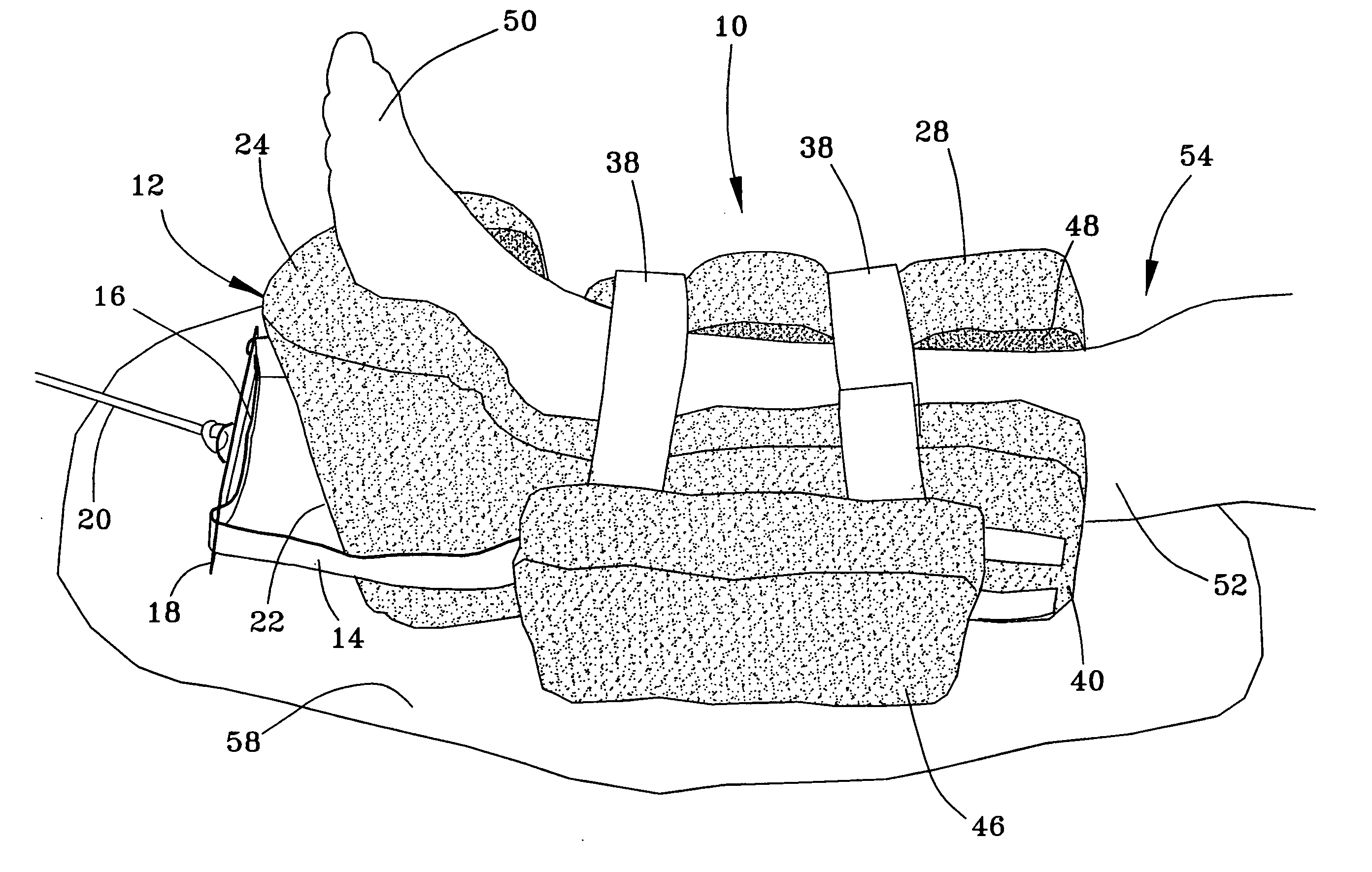
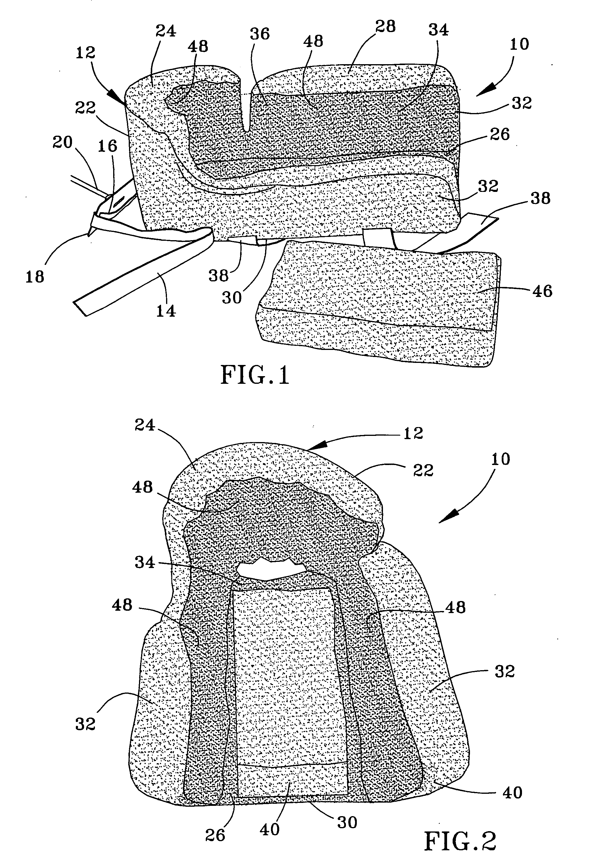
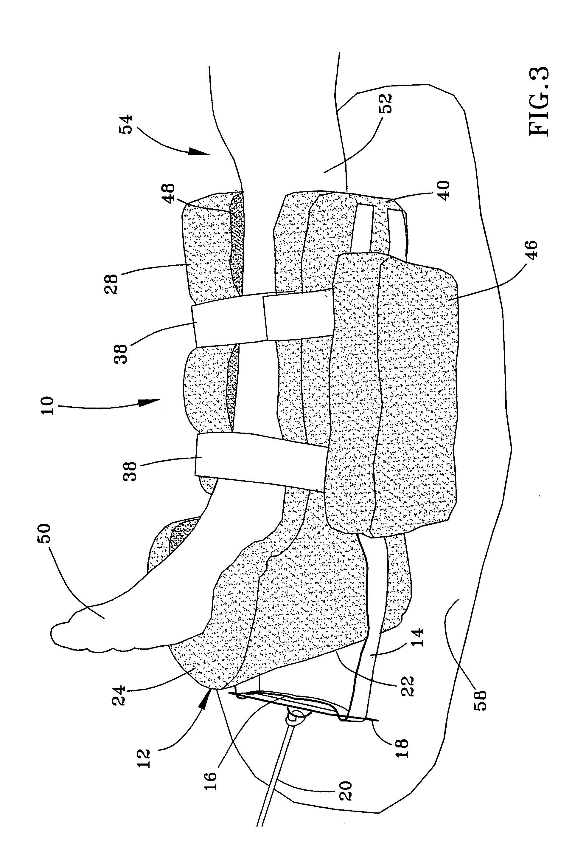
[0015]FIGS. 1 through 4 show a traction device 10 configured to be worn on a patient's foot 50 and lower leg 52 while the patient is in a generally supine position (reclining) on a bed 58 (the term “bed” is used herein to denote any surface on which a patient might recline while traction is applied to the patient's leg). The traction device 10 is configured to support the patient's heel 56 in a manner that avoids foot drop and relieves heel pressure to avoid heel or lateral malleolar pressure ulcers, while also being capable of transmitting full traction loads of up to ten pounds (about 45 N) to the patient's leg 54.

[0016] The present invention preferably makes use of a traction boot 12 that is configured similarly to a suspension boot commercially available under the name DM Systems HEELIFT®, which is disclosed in U.S. Pat. No. 5,449,339 to Drennan. The content of Drennan relating to the construction and composition of the suspension boot is incorporated herein by reference. The H...


PUM


Abstract

A traction device for applying traction to a patient's leg while supporting the patient's foot to avoid foot drop and heel or lateral malleolar pressure ulcers. The device includes a body having forefoot and lower leg portions, a continuous cavity within the forefoot and lower leg portions, and an anterior opening sized to permit a patient's foot and lower leg to pass therethrough into the cavity. The body supports the patient's lower leg so that the patient's heel is suspended within the cavity. Elements adjustably close the anterior opening and traction straps are removably attached to lateral regions of the body and extend from the forefoot portion. The interior surface of the cavity provides a sufficiently high friction interface with the patient's lower leg to prevent sliding of the body on the lower leg when full traction loads are applied through the traction straps.

Description

BACKGROUND OF INVENTION [0001] 1. Field of the Invention [0002] The present invention generally relates to a traction device for an extremity of a patient. More particularly, the invention is directed to a traction device adapted to support a patient's heel and reduce heel and malleolar pressure while the patient's leg is in traction. [0003] 2. Description of the Related Art [0004] Standard treatments of fractures of the femur include preoperative elevation on a pillow and preoperative traction. Traction typically involves skin traction by attaching to the sides of the leg a skin-tolerant device, which is then attached to a rope passing over a pulley to a weight of up to about ten pounds (about 4.5 kg or about 45 N). This type of traction is often referred to as “Buck's” traction. Skin traction devices may be applied to the skin in various ways, such as a “moleskin” held on the leg with elastic wraps. However, because of skin irritation, skin traction can typically be tolerated for ...

Claims


Application Information

Patent Timeline
Patent Type & Authority Applications(United States)
IPC IPC(8): A61F5/00
CPCA61F5/04
Inventor DRENNAN, DENIS BURKE
Owner DRENNAN DENIS BURKE
Why Eureka
Try Eureka