
Organic electroluminescence device and phenylenediamine derivative

Inactive Publication Date: 2006-04-20
IDEMITSU KOSAN CO LTD
View PDF12 Cites 20 Cited by
  • Summary
  • Abstract
  • Description
  • Claims
  • Application Information

AI Technical Summary

Benefits of technology

[0010] An object of the invention is to provide an organic EL device having a long life time that can decrease the driving voltage of the organic EL device.
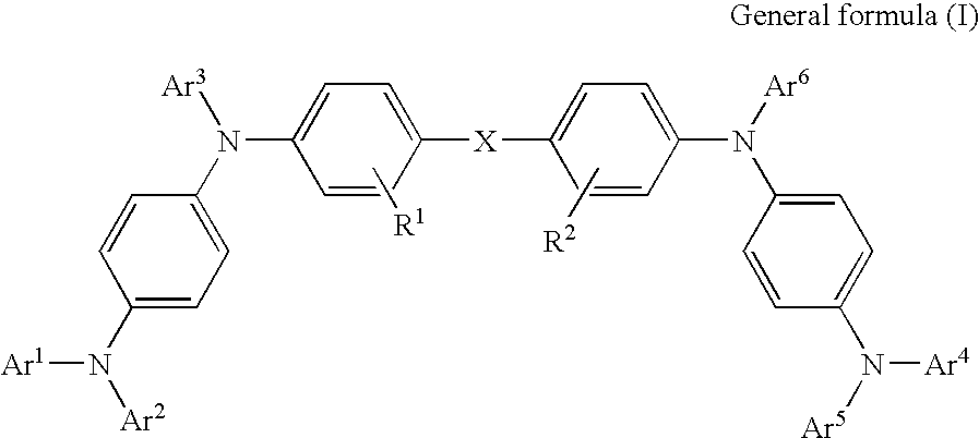
[0014] In the invention, the compound represented by the general formulae (I), (II) and (II)′ has a phenylenediamine skeleton and has a small ionization potential, and furthermore an excellent hole mobility can be ensured by the central skeleton shown by X and Y. In the invention, because the phenylenediamine derivative suitable as a hole injecting and transporting material is contained in the hole transporting zone, the driving voltage of the organic EL device can be decreased, and the increase of the driving voltage due to continuous driving can be suppressed.
[0016] The charge injection auxiliary herein means a compound having an ionization energy that is smaller than the ionization energy of the main material forming the light emitting layer, and preferably a material assisting hole injection by adding in an amount of from 0.1 to 20 wt % into the light emitting layer. By the addition of the charge injection auxiliary, the organic EL device of the invention can lower the driving voltage and also can stabilize the driving voltage. The use of the phenylenediamine and the addition of the charge injection auxiliary into the light emitting layer bring about the effect that has not been obtained.
[0017] As the charge injection auxiliary, a compound, such as a styrylamine derivative, a distyrylarylene derivative, a tristyrylarylene derivative, a diamine derivative and the like, can be used, and particularly, a compound having an ionization energy of from 5.0 to 5.6 eV is preferred. The charge injection auxiliary may emit light in response to the recombination of a hole and an electron occurring in the light emitting layer, or may exhibit the effect of assisting charge injection without emission of light.
[0020] In the foregoing, at least one of Ar1 to Ar6 in the general formula (I) is preferably a condensed aromatic ring having from 10 to 24 nucleus carbon atoms. According to this, the low voltage driving can be realized, and further the life time of the device can be prolonged.

Problems solved by technology

A problem on applying the organic EL device to a display is to make the driving voltage being a lower voltage.
However, the compound having a phenylenediamine skeleton has a small hole mobility of 3×10⁻⁵ cm2 / V·s, and therefore the driving voltage in the region of high electric current injection is insufficiently lowered.
A high molecular weight aromatic amine compound disclosed in JP-A-9-301934 has a small ionization potential of 5.2 eV but has a problem in that the hole mobility is insufficient.
Furthermore, the voltage is increased by 2.7 V with only driving time of 76 hours, which becomes a hindrance of lowering the driving voltage.
Furthermore, because it has a green fluorescent component, when the compound is used in the hole transporting zone of a blue light emitting device, blue light emission cannot be obtained due to mixing of green light emission component.

Method used


Image

  • Organic electroluminescence device and phenylenediamine derivative
  • Organic electroluminescence device and phenylenediamine derivative
  • Organic electroluminescence device and phenylenediamine derivative

Examples


example 1

Synthesis of 4-Iodotriphenylamine

[0145] 125 g of triphenylamine (produced by Hiroshima Wako & Co., Ltd.) was dissolved in 5 L of ethanol by heating, to which 150 g of mercury oxide was added at 60° C., and then 100 g of iodine was gradually added. Thereafter, the reaction was conducted for 2 hours at a reflux temperature.

[0146] After the reaction, the system was filtered under hot, and the residue was washed with acetone. The filtrate was cooled, and crystals thus deposited were filtered out.

[0147] It was purified by using a column carrying silica gel with toluene as a developing solvent, so as to obtain 52 g of objective substance.

(Synthesis of PD-01)

[0148] 10 g of 4,4″-diamino-p-terphenylene (produced by Lancaster Synthesis, Ltd.), 20 g of 1-iodonaphthalene (produced by Hiroshima Wako & Co., Ltd.), 20 g of potassium carbonate, 1 g of copper powder and 100 ml of nitrobenzene were placed in a 300-ml three-neck flask, and were heated under stirring at 200° C. for 48 hours.

[014...

example 2

(Synthesis of PD-02)

[0153] 10 g of 9,10-diaminophenylanthracene (produced by Wakayama Seika Industries, Ltd.), 20 g of 1-iodonaphthalene (produced by Hiroshima Wako & Co., Ltd.), 20 g of potassium carbonate, 1 g of copper powder and 100 ml of nitrobenzene were placed in a 300-ml three-neck flask, and were heated under stirring at 200° C. for 48 hours.

[0154] After the reaction, inorganic matters were filtered out, and the solvents in the mother liquid were distilled off. The residue was purified by using a column carrying silica gel (C-200 produced by Hiroshima Wako & Co., Ltd.) with toluene as a developing solvent, so as to obtain 7.7 g of 9,10-bis(1-naphthylaminophenyl)anthracene.

[0155] 5 g thereof, 15 g of 4-iodotriphenylamine, 20 g of potassium carbonate, 1 g of copper powder and 100 ml of nitrobenzene were placed in a 300-ml three-neck flask, and were heated at 200° C. for 60 hours.

[0156] After the reaction, inorganic matters were filtered out, and the solvents in the mothe...

example 3

(Synthesis of PD-03)

[0158] 10 g of 4,4′-diaminodiphenylmethane (produced by Hiroshima Wako & Co., Ltd.), 20 g of 1-iodonaphthalene (produced by Hiroshima Wako & Co., Ltd.), 20 g of potassium carbonate, 1 g of copper powder and 100 ml of nitrobenzene were placed in a 300-ml three-neck flask, and were heated under stirring at 200° C. for 48 hours.

[0159] After the reaction, inorganic matters were filtered out, and the solvents in the mother liquid were distilled off. The residue was purified by using a column carrying silica gel (C-200 produced by Hiroshima Wako & Co., Ltd.) with toluene as a developing solvent, so as to obtain 9.6 g of bis(4-(naphthyl-1-yl)aminophenyl)methane.

[0160] 5 g thereof, 15 g of 4-iodotriphenylamine, 20 g of potassium carbonate, 1 g of copper powder and 100 ml of nitrobenzene were placed in a 300-ml three-neck flask, and were heated at 200° C. for 60 hours.

[0161] After the reaction, inorganic matters were filtered out, and the solvents in the mother liqui...


PUM


Abstract

The invention is to provide an organic EL device having a long life time that can reduce the driving voltage of the organic EL device, and to provide a material having a small ionization potential and exhibiting a large hole mobility by using as a layer or a zone. The organic electroluminescence device comprises a pair of electrodes and an organic light emitting layer sandwiched in the electrodes, characterized in that a hole transporting zone provided between the electrodes comprises the phenylenediamine derivative represented by the specific structural formulae, and the phenylenediamine derivative has a hole mobility of 10−4 cm2 / V·s or more upon using as a layer or a zone, with the organic light emitting layer containing a charge injection auxiliary.

Description

[0001] This is a continuation application of U.S. application Ser. No. 10 / 331,645, filed Dec. 31, 2002, which is a divisional of U.S. application Ser. No. 09 / 530,597 filed May 9, 2000, which is National Stage of PCT / JP99 / 04794 filed Sep. 3, 1999.TECHNICAL FIELD [0002] The present invention relates to an organic electroluminescence device (hereinafter, referred to as organic EL device) and a phenylenediamine derivative, and more particularly, an organic EL device comprising a pair of electrodes and an organic light emitting layer sandwiched in the electrodes, and a phenylenediamine derivative used as a material for the organic EL device and the like. BACKGROUND ART [0003] An organic EL device is being earnestly studied since it is a complete solid state device and can form a display and an illumination of light-weight and thin-form that is driven at a low voltage. [0004] A problem on applying the organic EL device to a display is to make the driving voltage being a lower voltage. For...

Claims


Application Information

Patent Timeline
IPC IPC(8): H01J1/62C07C211/54C07C211/58C07C211/61C07C217/92C07D239/26C07D249/08C09K11/06H01L51/00H01L51/30H01L51/50H05B33/14H05B33/22
CPCC07C211/54C07C211/58C07C211/61C07C217/92C07C2103/18C07C2103/24C07D239/26C09K11/06C09K2211/1022H01L51/005H01L51/0052H01L51/0054H01L51/0058H01L51/0059H01L51/006H01L51/0061H01L51/0062H01L51/0067H01L51/0068H01L51/0069H01L51/007H01L51/0071H01L51/0081H01L51/5012H01L51/5048H01L51/5088H01L2251/308H05B33/14H05B33/22Y10S428/917C07C2603/18C07C2603/24H10K85/60H10K85/649H10K85/656H10K85/622H10K85/6565H10K85/655H10K85/636H10K85/626H10K85/633H10K85/631H10K85/615H10K85/324H10K85/654H10K85/657H10K50/14H10K50/17H10K50/11H10K2102/103
Inventor KAWAMURA, HISAYUKIHOSOKAWA, CHISHIO
Owner IDEMITSU KOSAN CO LTD
Learn More