
Bi-directional blowers for cooling computers

a laptop computer and bi-directional technology, applied in the direction of machines/engines, stators, liquid fuel engines, etc., can solve the problems of real challenge, less air driven, and less efficient centrifugal blowers

Inactive Publication Date: 2006-04-13
ZHENG WEN CHUN
View PDF8 Cites 47 Cited by
  • Summary
  • Abstract
  • Description
  • Claims
  • Application Information

AI Technical Summary

Benefits of technology

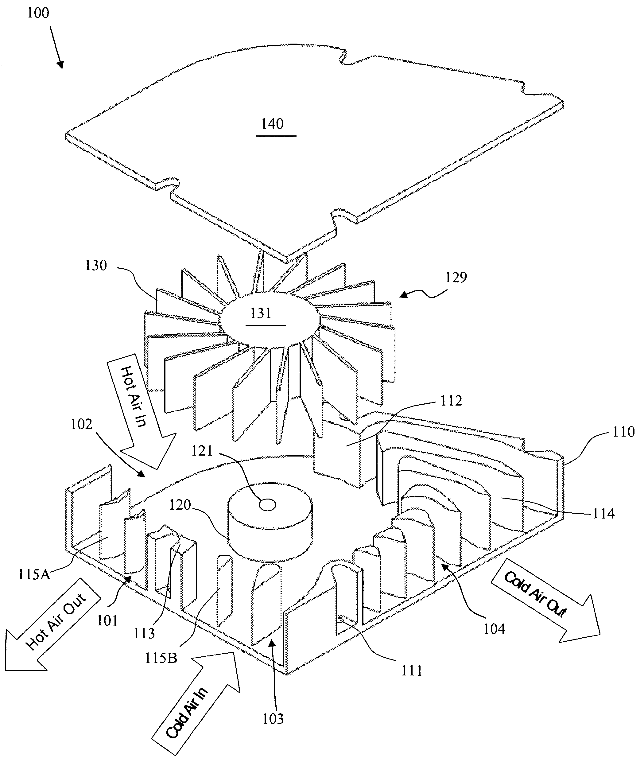
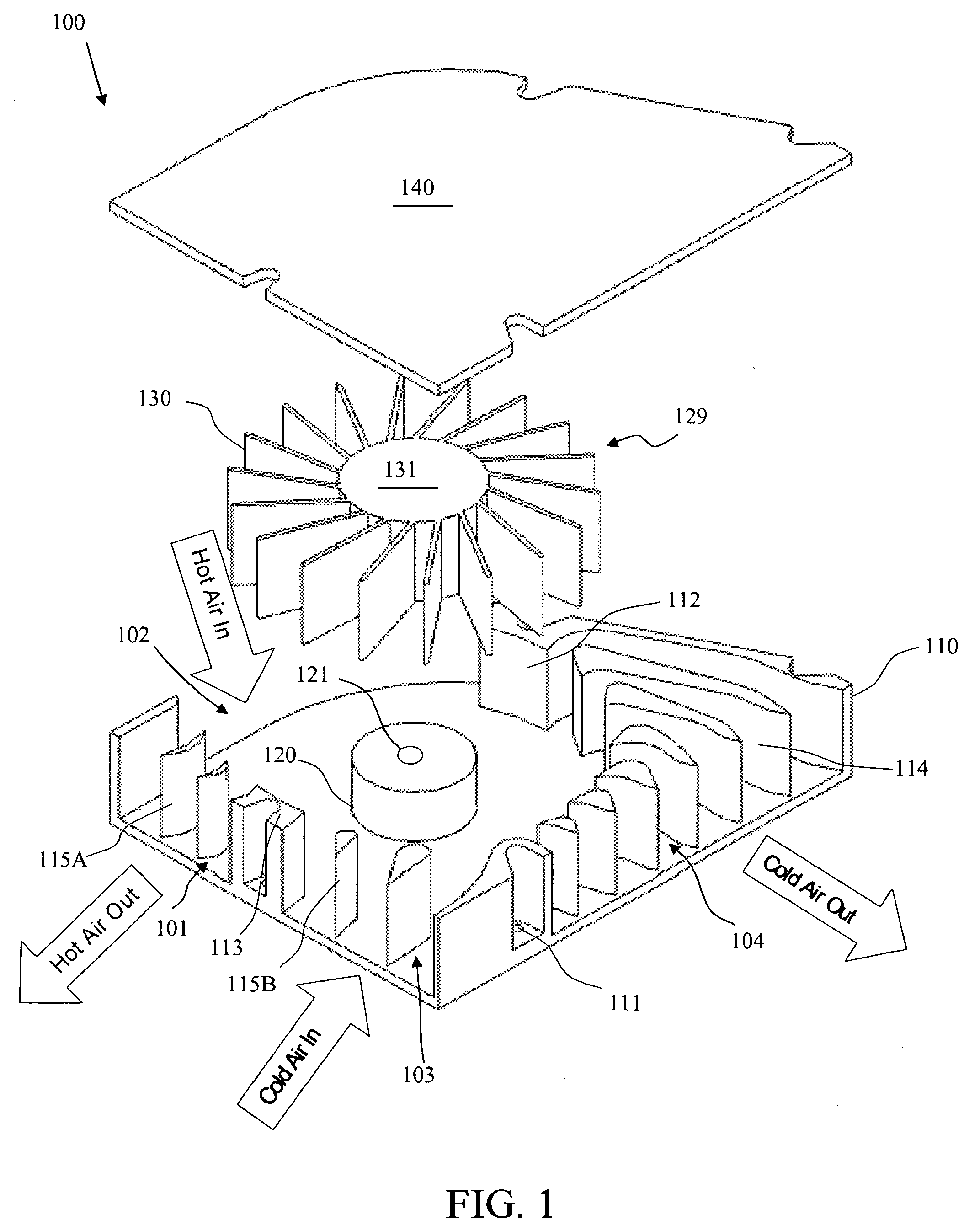
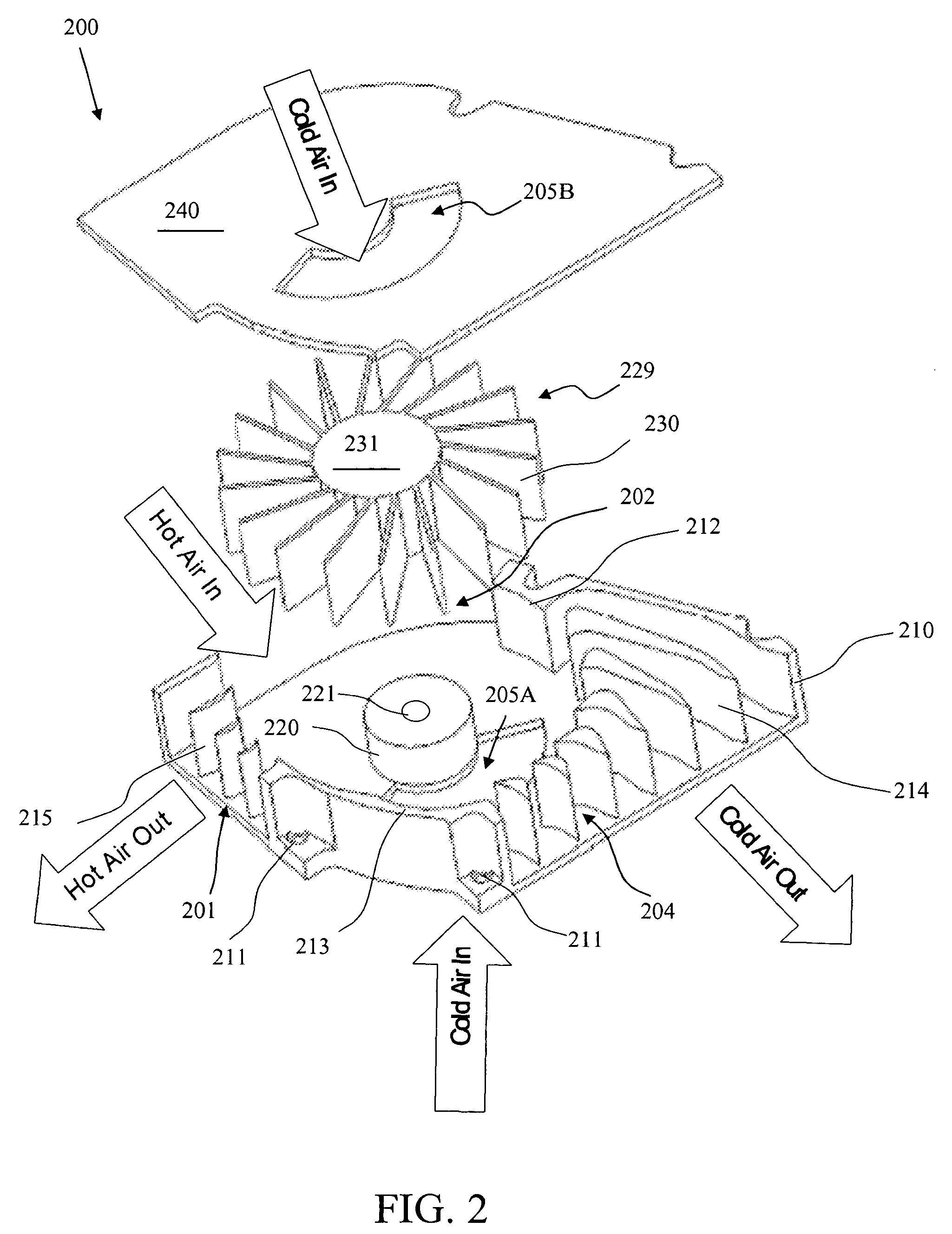
[0015] In one embodiment of the invention, a heat dissipating device includes a motor, a rotary unit, and a housing for receiving the motor and the rotary unit. The rotary unit includes a hub mounted to the motor and blades extending from the hub. The housing defines a hot air inlet, a hot air outlet, a cold air inlet, and a cold air outlet. The housing includes a first partition and a second partition located close to outer ends of the blades. The first and the second partitions divide the housing into (1) a first channel coupling the hot air inlet and the hot air outlet and (2) a second channel coupling the cold air inlet and the cold air outlet. The first and the second partitions have widths greater than a pitch of the blades to prevent air from mixing in the first and the second channels. The two channels create a bi-directional blower that removes hot air from and provides cold air into a computer case.

Problems solved by technology

However, this is a real challenge due to the compact design of the system box that fits many different components, such as CPU, PCI components, graphics processors, network processors, and memory.
A centrifugal blower is not as efficient as an axial fan of the same size because (1) the blower's inlet is smaller; (2) the air is driven less efficiently using centrifugal force generated by the fast rotation of the blades or impellers; (3) most of the air goes through a circular tunnel in the blower before it escapes through the outlet; and (4) the air experiences drag against the walls of the circular tunnel during its passage through the blower.
Overheating is a common problem for high power laptops.
Unfortunately, the air gap provides a large thermal resistance in the heat transfer path between the bottom of the laptop and the desktop.

Method used


Image

  • Bi-directional blowers for cooling computers
  • Bi-directional blowers for cooling computers
  • Bi-directional blowers for cooling computers

Examples


Embodiment Construction

[0016] One objective of the present invention is to provide a bi-directional blower that simultaneously blows hot air out from a system box and draws ambient air into the system box.

[0017] Another objective of the present invention is to provide airfoils in the inlet and the outlet of a blower to control air flow volume and velocity for more efficient air cooling.

[0018] Another objective of the present invention is to provide a bi-directional blower that can be used for space constrained conditions, such as in laptop computers, thin blade servers, and PCI cards (e.g., graphics cards), for efficient duct cooling.

[0019] Another objective of the present invention is to provide a bi-directional blower that draws air into the blower by “negative pressure” to enhance heat dissipation for a laptop computer where the inlets and outlets are located on the side of the laptop. Thus, the air gap between the bottom of the laptop and the desktop can be eliminated and the desk can serve as a na...


PUM


Abstract

A heat dissipating device includes a motor, a rotary unit, and a housing for receiving the motor and the rotary unit. The rotary unit includes a hub mounted to the motor and blades extending from the hub. The housing defines a hot air inlet, a hot air outlet, a cold air inlet, and a cold air outlet. The housing includes a first partition and a second partition located close to outer ends of the blades. The two partitions divide the housing into a first channel coupling the hot air inlet and the hot air outlet, and a second channel coupling the cold air inlet and the cold air outlet. The two partitions have widths greater than a pitch of the blades to prevent air from mixing in the two channels. The two channels create a bi-directional blower that removes hot air from and provides cold air into a computer case.

Description

CROSS-REFERENCE TO RELATED APPLICATIONS [0001] This application is a continuation-in-part of U.S. application Ser. No. 10 / 711,852, entitled “Bi-Directional Blowers for Cooling Laptop Computers,” filed Oct. 8, 2004, which is incorporated herein by reference.FIELD OF INVENTION [0002] This invention relates to the field of thermal management for computer and electronic systems, and more specifically to bi-directional blowers for cooling laptop computers. DESCRIPTION OF RELATED ART [0003] Fans and blowers are essential components in active air cooling of computer and electronic systems as the power of these systems increase. To improve air cooling, duct cooling is also utilized. As the heat density in a system is different in various zones, the ideal approach is to immediately remove heat from the hot region inside the system box through ducts to the outside. However, this is a real challenge due to the compact design of the system box that fits many different components, such as CPU, P...

Claims


Application Information

Patent Timeline
IPC IPC(8): F04D29/44F04D17/08F04D29/42
CPCF04D17/04F04D29/4246F04D29/444F04D25/0613F04D29/424
Inventor ZHENG, WEN-CHUN
Owner ZHENG WEN CHUN
Learn More