
Cyclone bypass for a circulating fluidized bed reactor

a fluidized bed reactor and cyclone bypass technology, which is applied in the direction of lighting and heating apparatus, combustion types, furnaces, etc., can solve the problems of high bottom ash content, high separation efficiency, and high process problems or drawbacks, so as to facilitate the change of fuel and provide operational flexibility , the effect of less heat loss

Inactive Publication Date: 2006-04-13
FOSTER WHEELER ENERGY CORP
View PDF8 Cites 11 Cited by
  • Summary
  • Abstract
  • Description
  • Claims
  • Application Information

AI Technical Summary

Benefits of technology

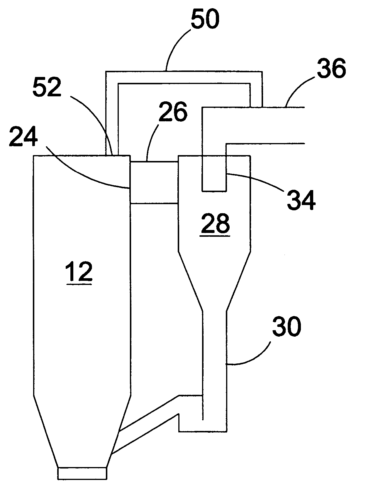
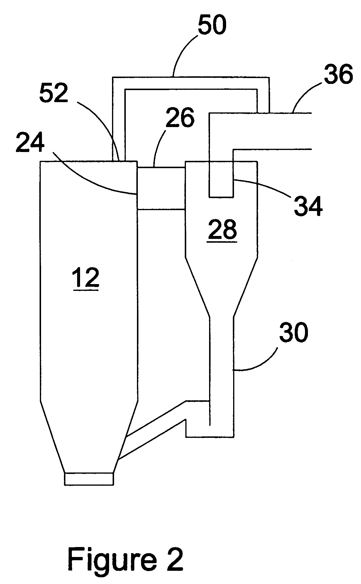
[0012] According to one aspect, the present invention provides a method of operating a circulating fluidized bed reactor having a firnace with a discharge port for exhaust gas, a particle separator connected to the discharge port and having an outlet for the exhaust gas and a return duct for the separated solids. The method comprises the steps of arranging a bypass duct bypassing the particle separator, and conducting a partial flow of exhaust gas along the duct for increasing the fly ash content in the exhaust gas after the separator.
[0013] In accordance with this method, the exhaust gas stream bypassing the particle separator decreases the amount of solid particles separated by the separator, whereby the solids inventory and the accumulation of bottom ash in the furnace are decreased.
[0014] According to another aspect, the present invention, provides an apparatus enabling the adjustment of the bed inventory such that the composition of the bed material may be kept in an optimal condition. Preferably, such an apparatus includes a furnace, a discharge port for removing exhaust gas with entrained solid particles from the furnace, a particle separator (preferably, a cyclone separator) connected to the discharge port for separating solid particles from the exhaust gas, the particle separator having an outlet for the exhaust gas connected to an exhaust gas duct and a solids outlet connected to a return duct for recycling the separated solid material back to the bottom of said furnace, and conducting a portion of the exhaust gas past the particle separator for decreasing the quantity of solid material entering the separator.
[0018] Accordingly, the present invention advantageously provides a novel and an improved method and apparatus for adjusting the composition of the bed material so that the amount of bottom ash is maintained within acceptable limits.
[0019] The present invention brings about numerous advantages in addition to the already mentioned smaller and less expensive bottom ash treatment apparatus. For instance, it provides operational flexibility to the furnace and, thus, allows changing the bottom ash and fly ash proportions, it is easier to make changes in the fuel, the heat loss is less, and it may be used for controlling the temperature and / or heat transfer in the furnace.

Problems solved by technology

However, very high separation efficiency may also bring about some problems or drawbacks in the process.
For instance, it may lead to a high bottom ash content compared to fly ash.
The more bottom ash that has to be removed from the reactor, the more expensive (i.e., of higher capacity) the equipment for both the discharge and the cooling of the bottom ash that is required.
Very high separation efficiency may also become a problem, e.g., when the quality of fuel varies in a way leading to the formation of an excessive amount of fine particles in the bed.
If the heat transfer rate exceeds its designed value, the bed has a tendency to cool to a lower temperature, leading, e.g., to increased emissions to the environment.

Method used


Image

  • Cyclone bypass for a circulating fluidized bed reactor
  • Cyclone bypass for a circulating fluidized bed reactor
  • Cyclone bypass for a circulating fluidized bed reactor

Examples


Embodiment Construction

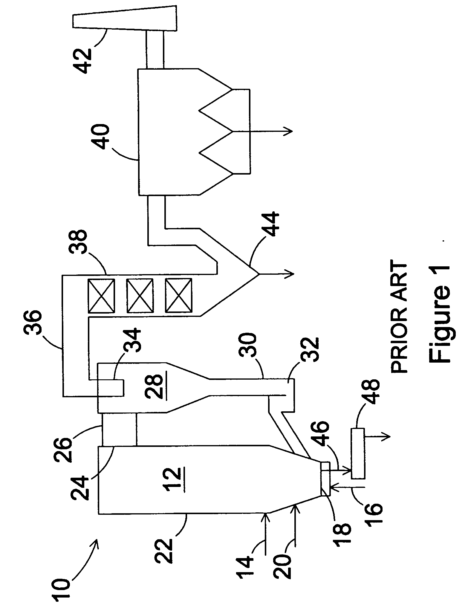
[0025] Referring now in greater detail to the drawings, in FIG. 1, the overall schematic of a typical circulating fluidized bed reactor system 10 is shown. Particulate fuel, inert bed material, and possible auxiliary material, such as limestone, are introduced to the furnace 12 of the reactor system 10 by solid material feeders 14, such as screw feeders or pneumatic feeders. The solid materials form a bed, which is fluidized by primary gas 16 introduced through a bottom grid 18. In a circulating fluidized bed, the velocity of the fluidizing gas in the furnace is typically from about 4 m / s to about 9 m / s. The reactions, such as combustion, of the fuel are completed by secondary gas 20 introduced through the sidewalls 22 of the furnace 12.

[0026] The reactions in the furnace 12 produce gases, such as flue gases, which are discharged together with particles entrained with the gases from the furnace 12 through a discharge port 24 to a discharge duct 26, and further to a particle separat...


PUM


Abstract

A method of and an apparatus for operating a circulating fluidized bed reactor having a furnace with a discharge port for exhaust gas, and a particle separator having an inlet connected to the exhaust gas discharge port and an outlet duct for the exhaust gas and a return duct for separated solids. The method includes the steps of arranging a bypass duct bypassing the particle separator, and conducting a partial flow of exhaust gas along the duct for increasing the fly ash content in the exhaust gas after the separator. The bypass duct is advantageously provided with means for controlling the flow of exhaust gas in the bypass duct.

Description

BACKGROUND OF THE INVENTION [0001] 1. Field of the Invention [0002] The present invention relates to a method of and an apparatus for operating a circulating fluidized bed reactor having a separator for separating entrained solid particles from the exhaust gas and recycling the separated particles to the combustion chamber. The invention particularly relates to the composition of the bed material, and seeks to solve problems relating to the control of bed inventory and bottom ash quantity. [0003] 2. Description of the Related Art [0004] Circulating fluidized bed reactors have been used for decades and are known to those skilled in the art of power generation, for instance. The circulating fluidized bed reactors may be gasifiers, combustors, steam generators, or any other similar type of apparatus as those skilled in the art will recognize. The fluidized bed reactors normally have an upright furnace, or reaction chamber, to the lower part of which the fuel is introduced. Primary and ...

Claims


Application Information

Patent Timeline
IPC IPC(8): F23D1/00F23G1/00
CPCF23C10/10
Inventor GOUNDER, PONNUSAMI K.
Owner FOSTER WHEELER ENERGY CORP
Learn More