
Glenoid instrumentation and associated method

Inactive Publication Date: 2006-04-06
DEPUY PROD INC
View PDF98 Cites 46 Cited by
  • Summary
  • Abstract
  • Description
  • Claims
  • Application Information

AI Technical Summary

Benefits of technology

[0020] Another embodiment of the present invention may be in the form of a wedged shaped sizer disk that can be utilized on cases where there is Type C erosion. This disk will show the surgeon a more anatomical version, if not the correct version. Such a wedged shaped disk will allow the surgeon to size the implant necessary for such patients. This is necessary since due to the shape of the glenoid, as one moves more medially, the surface area of the glenoid fossa decreases. To make an attempt to return the glenoid to its anatomical version would result in excessive bone loss. The instruments of the present invention allow the surgeon to make an assessment of the proper size of the step cut for the glenoid that will be needed to correct the defect.
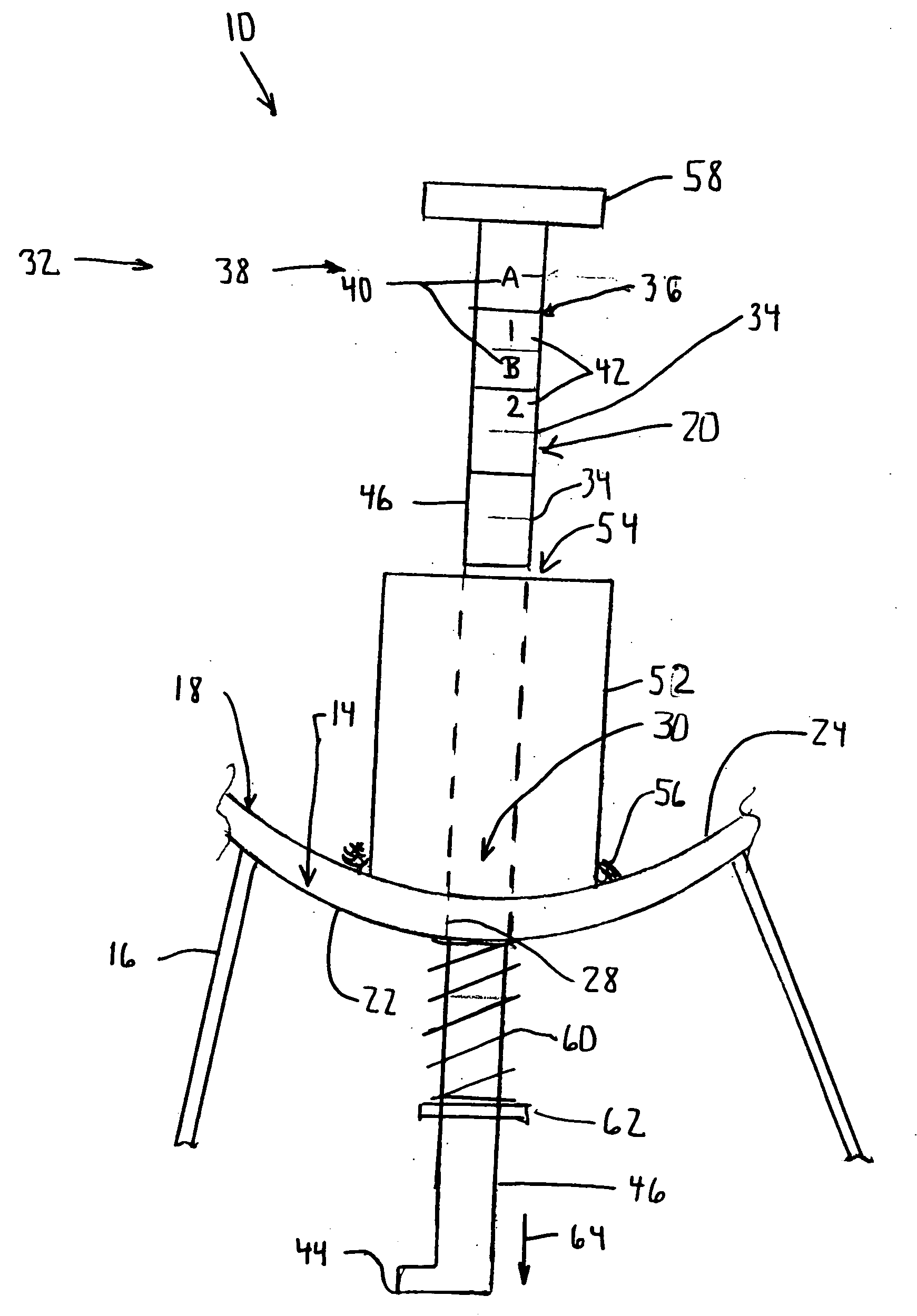
[0021] Another embodiment of the present invention is a sizer disk with a depth gage positioned on the posterior rim of sizer disk. The depth gauge may be in the form of a needle type depth gauge. This depth gauge allows the surgeon to properly size the glenoid to the existing bone and to measure the size of the step that will be required to correct the defect with the least amount of bone loss.
[0022] Since it is anticipated these devices will be used with a step cut glenoid system, they may be marked by etching, or other means, to determine the exact position of the central edge of the step augment. Such marking may aide the surgeon in assessing the glenoid for proper treatment.
[0028] The technical advantages of the present invention include the ability to accurately characterize a posterior defect. Such accurate characterizing of the posterior defect can be used to choose the appropriate glenoid implant for a posterior defect. For example, according to one aspect of the present invention an instrument for measuring a defect in a glenoid fossa of a scapula is provided. The instrument includes a member for contact with the glenoid fossa and a probe. The probe is removably associated with the member. The probe is operably associated with the defect for measuring the defect in the bone. Thus the present invention provides for an instrument which has an ability to accurately characterize a posterior defect.

Problems solved by technology

Such erosion of the scapula renders treatment difficult, if not impossible, with a conventional glenoid prosthesis.
For example, the relatively smooth, arcuate-shaped medial surface may over time lead to loosening of the augmented glenoid component, thereby potentially necessitating additional surgical procedures to replace or reseat the component.
Further, due to the configuration of the medial surface, a relatively high shear load is created along the implant-to-bone interface when the component is implanted.
The presence of a high shear load along the implant-to-bone interface tends to also cause loosening of the component 100 over a period of time.
Post-operative loosening is the largest cause of failures of implanted glenoid components.
The design of this augmented glenoid component, however, suffers from at least the same drawbacks as the glenoid component.
Such a procedure leaves little supporting bone.
Furthermore, because the little supporting bone is left there is almost no support bone available for a revision surgery if necessary.
Such loading on the posterior edge can lead to loosing and failure of the glenoid component.
Such a bone wedged graft is technically difficult and has an inherent risk of failure.
There are currently no devices to provide the necessary information to the surgeon to aid in the implantation of these devices.
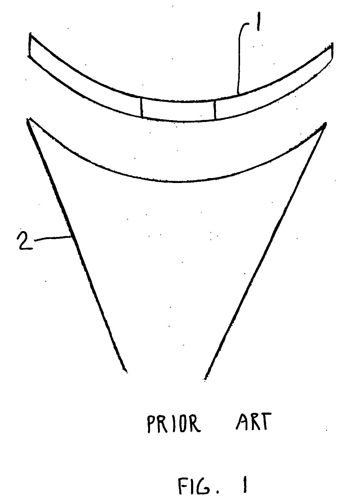
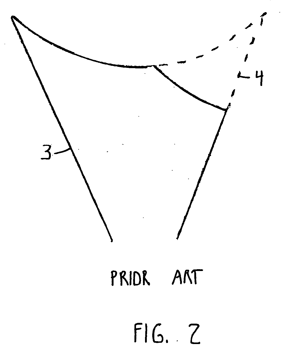
Also, the fit of the prior art sizer disk 1 on the natural glenoid fossa 3 may be difficult to determine due to its shortened contact area.

Method used


Image

  • Glenoid instrumentation and associated method
  • Glenoid instrumentation and associated method
  • Glenoid instrumentation and associated method

Examples


Embodiment Construction

[0055] Embodiments of the present invention and the advantages thereof are best understood by referring to the following descriptions and drawings, wherein like numerals are used for like and corresponding parts of the drawings.

[0056] According to the present invention and referring now to FIG. 7 instrument 10 according to the present invention is shown. The instrument 10 is utilized for measuring a defect 12 as shown in phantom in a glenoid fossa 14 of a scapula 16. The instrument 10 includes a member 18 for contact with the glenoid fossa 14. The instrument 10 further includes a probe 20 moveably associated with the member 18. The probe 20 is operably associated with the defect 12 for measuring the defect 12 in the scapula 16.

[0057] As shown in FIG. 7 the member 18 may include a convex surface 22 for contact with glenoid fossa 14. For simplicity as shown in FIG. 7 the member 18 may be in the form of a curved plate having an opposed surface 24 opposed to the convex surface 22. The...


PUM


Abstract

An instrument for measuring a defect in a glenoid fossa of a scapula is provided. The instrument includes a member for contact with the glenoid fossa and a probe. The probe is moveably associated with the member. The probe is operably associated with the defect for measuring the defect in the scapula.

Description

TECHNICAL FIELD OF THE INVENTION [0001] The present invention relates generally to the field of orthopaedics, and more particularly, to an implant for use in arthroplasty. CROSS-REFERENCE TO RELATED APPLICATIONS [0002] Cross reference is made to the following applications: DEP 5070 entitled “EXTENDED ARTICULATION PROSTHESIS ADAPTOR AND ASSOCIATED METHOD”, DEP 5072 entitled “GLENOID AUGMENT AND ASSOCIATED METHOD”, DEP 5304 entitled “INSTRUMENT FOR PREPARING AN IMPLANT SUPPORT SURFACE AND ASSOCIATED METHOD”, DEP 5306 entitled MODULAR GLENOID PROSTHESIS AND ASSOCIATED METHOD”, and DEP 5307 entitled “GLENOID INSTRUMENTATION AND ASSOCIATED METHOD”, filed concurrently herewith which are incorporated herein by reference. BACKGROUND OF THE INVENTION [0003] During the lifetime of a patient, it may be necessary to perform a total shoulder replacement procedure on the patient as a result of, for example, disease or trauma. In a total shoulder replacement procedure, a humeral component having a...

Claims


Application Information

Patent Timeline
IPC IPC(8): A61B5/103
CPCA61B5/036A61B5/103A61B5/107A61B5/4528A61F2/4081A61F2/4612A61F2/4657A61F2/4684A61F2002/30331A61F2002/30565A61F2002/30617A61F2002/4658A61F2002/4666A61F2002/4672A61F2220/0033A61F2250/0097A61F2310/00011A61F2310/00179
Inventor DEFFENBAUGH, DAREN LLOYDCAMINO, THOMAS SCOTT
Owner DEPUY PROD INC
Learn More