
Phased array acoustic system for 3d imaging of moving parts

a phased array and moving part technology, applied in the field of ultrasound and phased array imaging systems, to achieve the effects of reducing acquisition time, dividing acquisition time, and reducing acquisition tim

Inactive Publication Date: 2006-04-06
KONINKLIJKE PHILIPS ELECTRONICS NV
View PDF53 Cites 137 Cited by
  • Summary
  • Abstract
  • Description
  • Claims
  • Application Information

AI Technical Summary

Benefits of technology

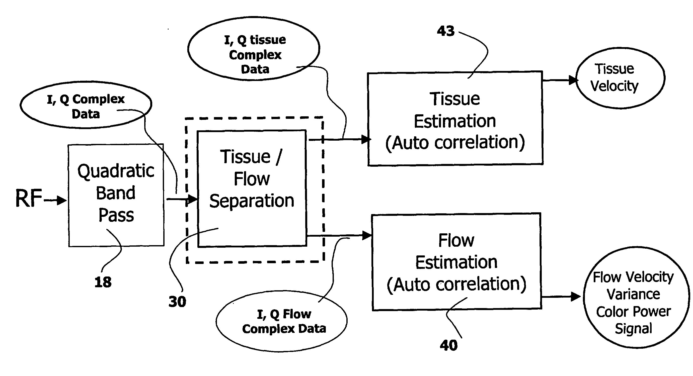
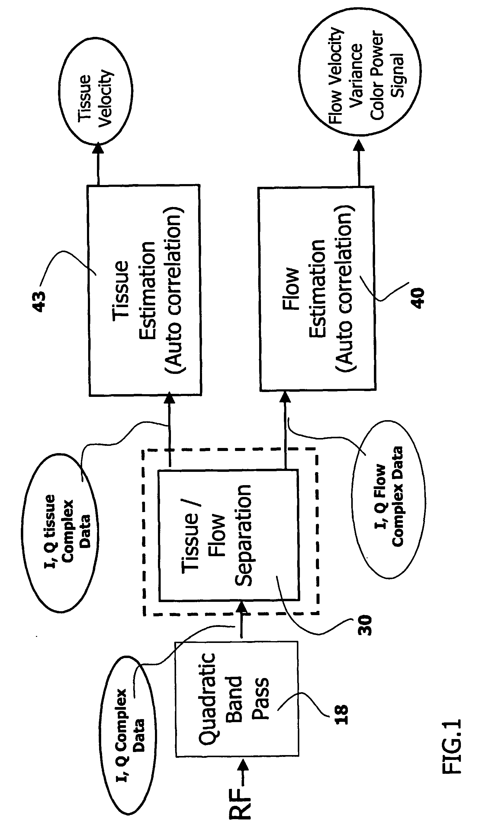
[0012] The ultrasound viewing system of the invention comprises means to minimize the acquisition time duration with respect to the known systems. The number of temporal samples, i. e. successive signals along a transmission beam, is defined as an “ensemble length”. This system comprises means to reduce to 3 or 4 the number of successive signals out of the eight signals previously required. This operation reduces the acquisition time, possibly dividing the acquisition time by more than two. This system is able to provide four to sixteen reception beams for one emission beam, which multiplies by one to four the scanned volume at each transmission. Hence, The total acquisition time gain is then a factor of two to ten. The fact that few temporal samples are used is compensated by the fact that a larger number of spatial samples is available. A target receives an only emission beam and is examined using more than one received beams, for example four to sixteen received beams in parallel, which see this target differently, and with more than two temporal samples, for example three to four successive transmissions, which allows to analyze the temporal variations of the successive signals, due to the displacement of the target.

Problems solved by technology

The systems described as prior art do not permit to form 3-D Doppler images of a fluid flow of a body in real time in the volume called volume of reference, because this operation would necessitate multiplying the acquisition time by eight with respect to the acquisition time for forming 3-D gray images.

Method used


Image

  • Phased array acoustic system for 3d imaging of moving parts
  • Phased array acoustic system for 3d imaging of moving parts
  • Phased array acoustic system for 3d imaging of moving parts

Examples


Embodiment Construction

[0020] The invention relates to an ultrasound, phased array imaging system and, more particularly, to an imaging system, which uses a transducer array with transducer elements in a 2-D arrangement. For example, the transducer elements are disposed in a 2-D arrangement in a 2-D plane. This ultrasound viewing system has means to form real time 3-D Doppler color images of moving parts of a body, for instance for imaging a fluid flow, such as a blood flow in a vessel or in the heart; or for imaging tissue motion such as heart walls.

[0021] This ultrasound viewing system has means to divide by two to ten the acquisition time duration with respect to conventional ultrasound systems. This ultrasound viewing system comprises means to multiply by four to sixteen the number of beams in the reception phase. Hence, said system provides more than one reception beams, for example four to sixteen reception beams for one emission beam, which multiplies by one to four a scanned volume at each transm...


PUM


Abstract

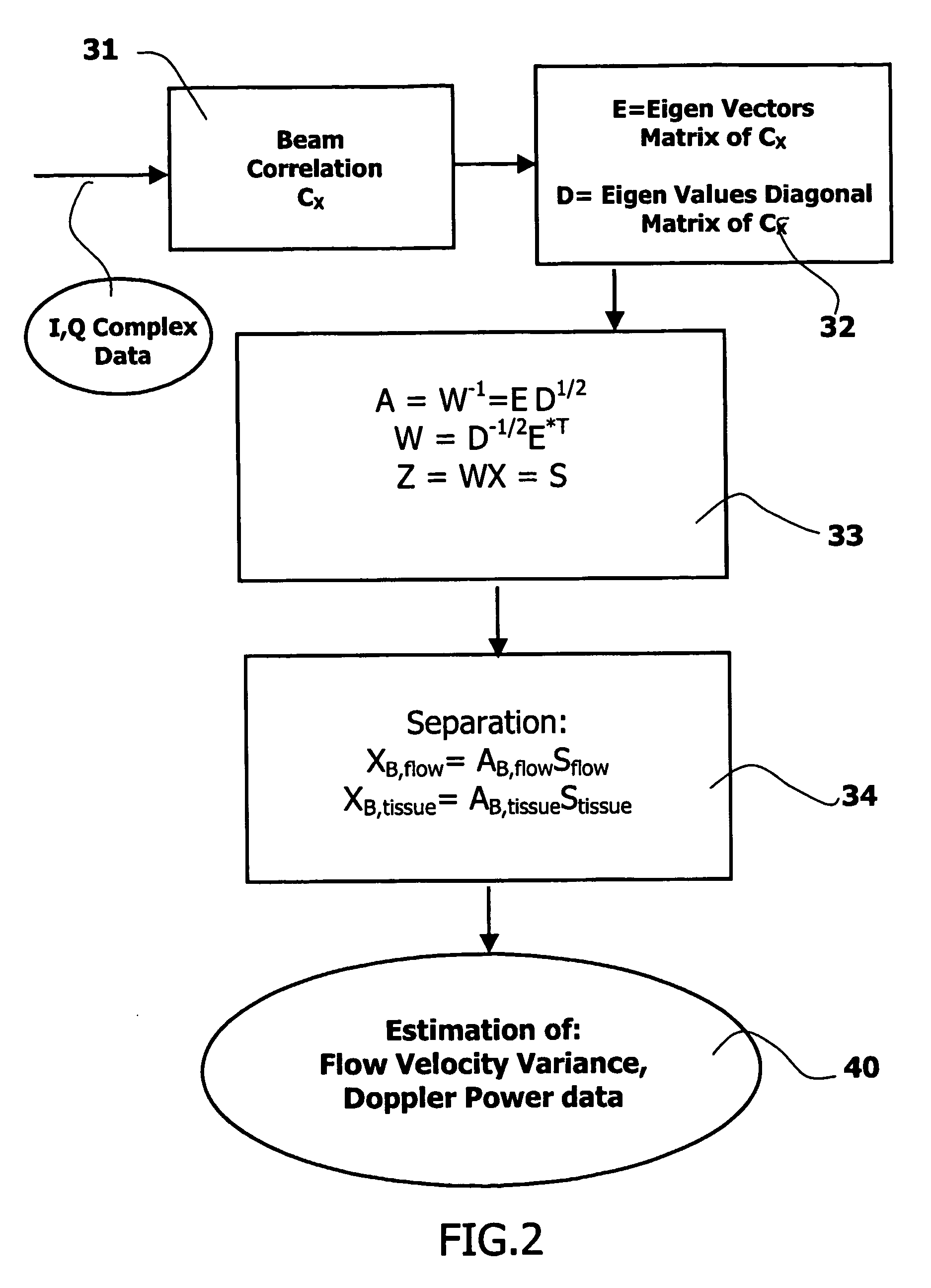
The invention relates to an ultrasound phased array imaging system comprising: probe (10) with a 2-D array of transducer elements (12) for acquiring 3-D ultrasound data of a volume of a body, including moving tissue and fluid flow; a beamforming system (10, 12, 14, 16) for emitting and receiving in real time ultrasound beams in said volume, which provides, in real time and in 3-D, more than one spatial receive beams signals for each transmission beam within an ensemble length of more than two temporal samples, among which the receive flow beam signals and the receive tissue beam signals are substantially temporally uncorrelated but spatially correlated; separation means (30) for processing in real time the receive beams signals, comprising adaptive spatial tissue filtering means using simultaneously more than one spatial receive beam signals acquired in 3-D within the ensemble length of more than two temporal samples, which separation means analyzes temporal variations of the respective successive receive signals and extracts flow receive beam signals from spatial combinations of receive beam signals; processing means (40, 50) and display means (62, 60) for processing flow Doppler signals and for displaying images based on said processed flow Doppler signals.

Description

FIELD OF THE INVENTION [0001] The invention relates to an ultrasound, phased array imaging system and more particularly, to an imaging system, which uses an ultrasound transducer array with a 2D arrangement of transducer elements, having means to form 3-D motion images of moving parts of a body. These moving parts are typically blood flows and moving tissues like arterial or cardiac walls. [0002] The invention particularly finds applications in the field of medical ultrasound imaging. BACKGROUND OF THE INVENTION [0003] Various methods and devices have been proposed for ultrasonically scanning a volume within a subject for three-dimensional imaging and display. Many of these techniques involve the scanning of a number of spatially adjacent image planes of a region of the body. The ultrasonic information from these associated planes can be analyzed and displayed on the basis of spatial coordinates of the data within a plane, and on the basis of the spatial relationship of each plane t...

Claims


Application Information

Patent Timeline
IPC IPC(8): A61B8/00G01S7/52G01S15/89
CPCG01S7/52038G01S7/5206G01S7/52068G01S7/52071A61B8/483G01S7/52095G01S15/8925G01S15/8981G01S15/8993G01S7/52073
Inventor BONNEFOUS, ODILE
Owner KONINKLIJKE PHILIPS ELECTRONICS NV
Learn More