
Snap in place gasket for sealing plastic pipelines and method of installation

Inactive Publication Date: 2006-04-06
S & B TECHN PRODS
View PDF13 Cites 29 Cited by
  • Summary
  • Abstract
  • Description
  • Claims
  • Application Information

AI Technical Summary

Benefits of technology

[0015] Another object of the invention is to provide an improved gasket installation appa

Problems solved by technology

Each of these solutions was less than ideal, in some cases failing to provide the needed joint integrity and often contributing to the complexity and expense of the manufacturing operation.
Despite the advances offered by the Rieber process, the belling operation was somewhat complicated and costly.
While such retaining bands helped to resist axial forces acting on the gasket during assembly of the joint, the band could become displaced or twisted during the insertion operation.
However, gaskets with embedded reinforcing rings are not easily bent or flexed by hand, thus generally precluding hand assembly in the field.
The size and position of the embedded ring within the gasket body generally was greater than the diameter of the mouth opening of the belled pipe end, presenting a further complication for assembly.
However, such a machine was fairly costly to construct and was not capable of being hand carried by a worker in the field.

Method used


Image

  • Snap in place gasket for sealing plastic pipelines and method of installation
  • Snap in place gasket for sealing plastic pipelines and method of installation
  • Snap in place gasket for sealing plastic pipelines and method of installation

Examples


Embodiment Construction

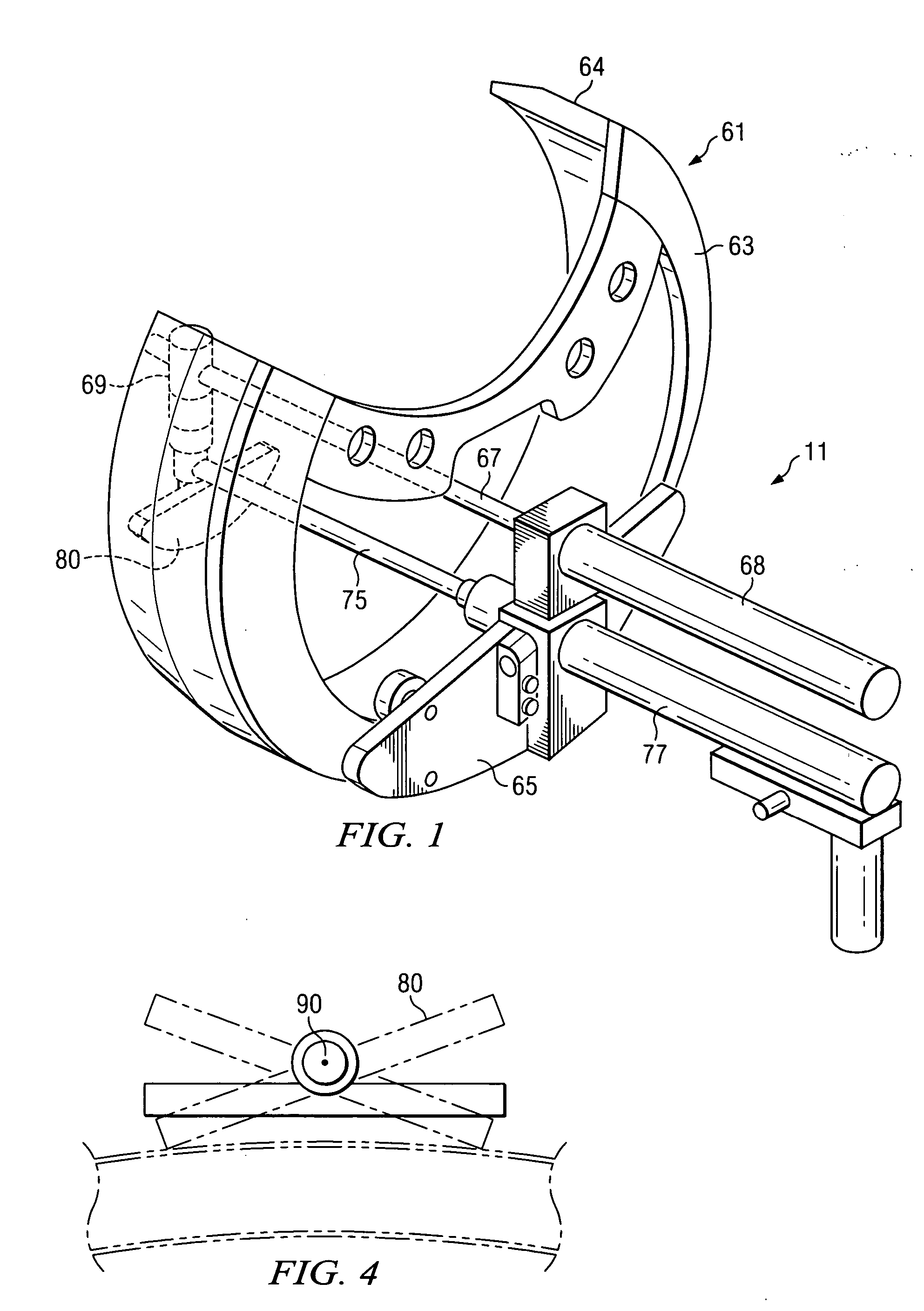
[0030] Turning now to the attached illustrations, FIGS. 1 and 5 show the gasket of the invention and an installation apparatus used in the method of the invention. The apparatus 11 (FIG. 1) is used to install a gasket (13 in FIG. 5) within a gasket receiving groove (15 in FIGS. 2 and 5) provided within the belled end 17 of a section of thermoplastic pipe 19. The pipe section 19 can be formed of any of a variety of commercially available thermoplastic materials, such as the polyolefin family including polyethylene and polypropylene as well as polyvinyl chloride and similar materials. Thermoplastic pipes of this general type are used in a variety of industrial settings including water, sewage and chemical industries. The belled end 17 of the thermoplastic pipe section has a mouth opening 21 (FIGS. 2 and 5) which is engageable with a spigot end (not shown) of a mating pipe section to form a pipe joint. The gasket receiving groove 15 has been pre-formed in the pipe mouth opening 21 at t...


PUM

PropertyMeasurementUnit
Angleaaaaaaaaaa
Thicknessaaaaaaaaaa
Diameteraaaaaaaaaa

Abstract

A pipe sealing gasket is shown which is designed to be received within a groove provided within a belled, socket end of a plastic pipe. The groove in the plastic pipe is preformed during manufacture and the gasket is installed thereafter. The gasket nominal diameter exceeds the internal diameter of the belled pipe end. A special installation tool is used to pull the gasket from an initially deformed, elliptical shape to a normal cylindrical shape. The installation tool uses only one fluid cylinder for power and can be hand installed and operated.

Description

CROSS REFERENCE TO RELATED APPLICATIONS [0001] The present application claims priority from earlier filed provisional application Ser. No. 60 / 616,463, filed Oct. 6, 2004, entitled “Snap In Place Gasket for Sealing Plastic Pipelines and Method of Installation,” by Bradford G. Corbett, Jr.BACKGROUND OF THE INVENTION [0002] 1. Field of the Invention [0003] The present invention relates generally to sealing gaskets and sealing systems used for pipe joints in plastic pipelines in which a male spigot pipe section is installed within a mating female socket pipe section to form a pipe joint and, more specifically, to an improved gasket and installation method for installing a locked-in gasket within a preformed gasket groove in a section of pipe used to form a pipe joint. [0004] 2. Description of the Prior Art [0005] Fluid sealing systems for plastic, fluid conveying pipes are used in a variety of industries. The pipes used in such systems are typically formed from thermoplastic materials i...

Claims


Application Information

Patent Timeline
IPC IPC(8): F16L21/02
CPCB25B27/0028F16L21/03Y10S277/944Y10T29/49876Y10T29/49872Y10T29/53909Y10T29/54Y10S277/939
Inventor CORBETT, BRADFORD G. JR.
Owner S & B TECHN PRODS
Learn More