
Method and device for designing a data network

a data network and data technology, applied in data switching networks, frequency-division multiplexes, instruments, etc., can solve the problems of increasing the difficulty of demand forecasting, reducing the efficiency of the network day after day, and hardly predicting demand

Inactive Publication Date: 2006-03-30
TELECOM ITALIA SPA
View PDF10 Cites 9 Cited by
  • Summary
  • Abstract
  • Description
  • Claims
  • Application Information

AI Technical Summary

Problems solved by technology

Afterwards, as the demand pattern changes from the pattern considered during the initial planning phase, it is likely that the efficiency of the network decreases day after day.
It follows that, in a conventional network, forecast of the demand is hardly possible.
Moreover, in multimedia networks of recent years, demand forecast has become more and more difficult.
Currently, the re-design of computer networks, particularly wide area networks, is a complex procedure requiring specialist trained staff.
As a consequence the network configuration, as well as the architecture of single nodes, grows in an irregular, confused and very expensive way.

Method used


Image

  • Method and device for designing a data network
  • Method and device for designing a data network
  • Method and device for designing a data network

Examples


Embodiment Construction

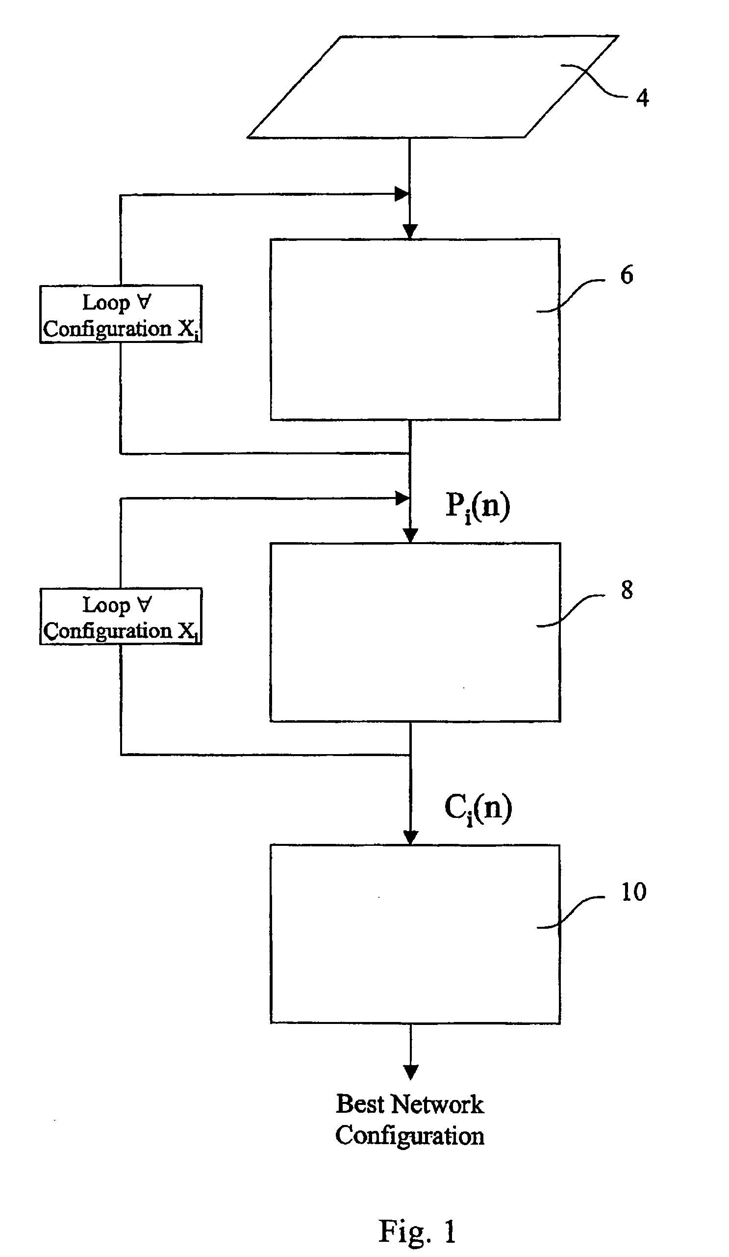
[0023] With reference to the flow diagram of FIG. 1, a network design and analysis method allowing to evaluate the flow's cost for different network structures will be described herein below.

[0024] As a first step (block 4 in diagram of FIG. 1) it is necessary to define a plurality of alternative network configurations, each configuration being defined by a plurality of network elements interconnected by a plurality of connections.

[0025] For each network under study, the following input data have to be specified:

[0026] number of nodes / equipments inside the network;

[0027] number and typologies of the links (real or hypothetical) between nodes / equipments.

[0028] A first network configuration can be, for example, the configuration of an existing network which will be compared with a number of alternative network configurations, in case the design method is used for optimising an existing network or node; otherwise the method according to the invention can be used as a design tool f...


PUM


Abstract

A method of designing a transport network having a plurality of network elements and a plurality of connections between the network elements by (a) defining a first network configuration and at least one alternative network configuration for the same transport network; (b) calculating for each network configuration, a probability function representing, for each maximum number of routable flows, the probability of routing such a number of flows in the network configuration currently considered; (c) calculating for each network configuration, a unit-cost-per-flow function calculated as the ratio between a sum of the costs relative to the network elements of the network configuration currently considered and the probability function; and (d) comparing the unit-cost-per-flow functions of the network configurations considered, for choosing a network configuration having a lowest unit-cost-per-flow value.

Description

FIELD OF THE INVENTION [0001] The present invention refers to a method and a device for designing a transport network. BACKGROUND ART [0002] According to conventional communication network design methods, an optimum design of a network is conducted only when a new network is planned for the first time. During the design process, path and link capacities of a network are designed for a given specific traffic demand. For a given predetermined demand pattern an optimisation of the network design is conducted, and an optimum network minimizing the cost is designed. Afterwards, as the demand pattern changes from the pattern considered during the initial planning phase, it is likely that the efficiency of the network decreases day after day. [0003] In actual telecommunication networks, indeed, the demand pattern varies very frequently, depending upon changes in client subscriptions or changes in traffic load due to the widespreading of new communication services or the introduction of new...

Claims


Application Information

Patent Timeline
IPC IPC(8): H04J3/14H04L12/24H04L12/701
CPCH04L12/24H04L45/00H04L41/00
Inventor BOSSI, MARIACHIARAALLASIA, ANDREAVARETTO, LUIGI GIUSEPPERITA, ROBERTO
Owner TELECOM ITALIA SPA
Learn More