Circuit arrangement for operating at least one light source

a circuit arrangement and light source technology, applied in the direction of electric variable regulation, process and machine control, instruments, etc., can solve the problems of the problem of not being able to adhere to the relevant standards for the line current harmonic, and the limitation value of line current harmonics. to achieve the effect of further reducing the factor produced during the operation of the lamp

Inactive Publication Date: 2006-03-23
PATENT TREUHAND GESELLSCHAFT FUR ELECTRIC GLUEHLAMPEN MBH
View PDF5 Cites 8 Cited by
  • Summary
  • Abstract
  • Description
  • Claims
  • Application Information

AI Technical Summary

Benefits of technology

[0026] The present invention is therefore based on the object of developing a circuit arrangement for operating at least one light source on the basis of the topo

Problems solved by technology

Standards such as IEC 61000-3-2 also prescribe, however, limit values for line current harmonics.
Above 25 W, however, it is problematic to adhere to the relevant standards for the line current harmonics.
The adherence to this limit value at a power consumed from the power supply system of above 25 W is an additional problem.
This leads to an increase in costs, to g

Method used


Image

  • Circuit arrangement for operating at least one light source
  • Circuit arrangement for operating at least one light source

Examples


Embodiment Construction

[0042] In the text which follows, transistors will be denoted by the letter T, diodes by the letter D, capacitors by the letter C, inductors by the letter L, resistors by the letter R and connections by the letter J, in each case followed by a number.

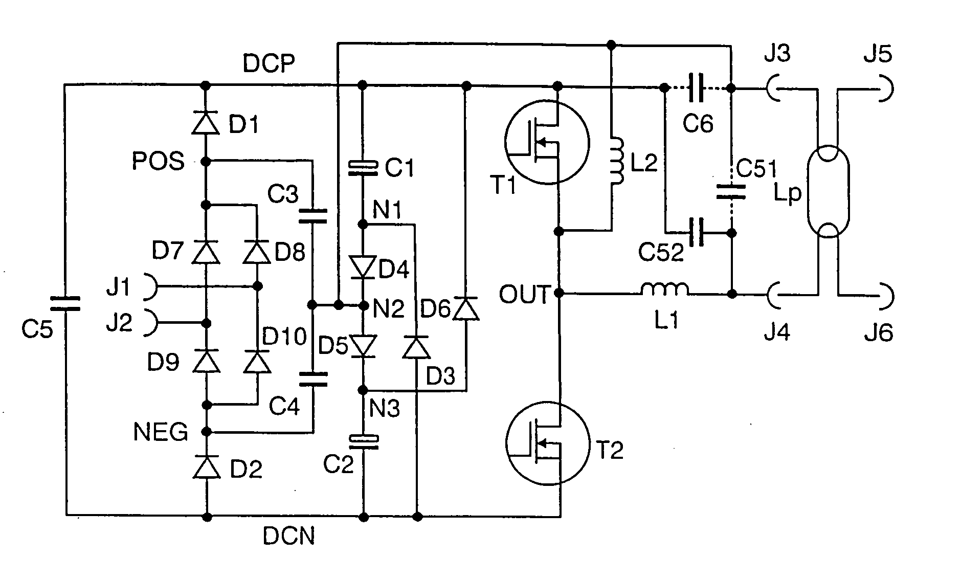
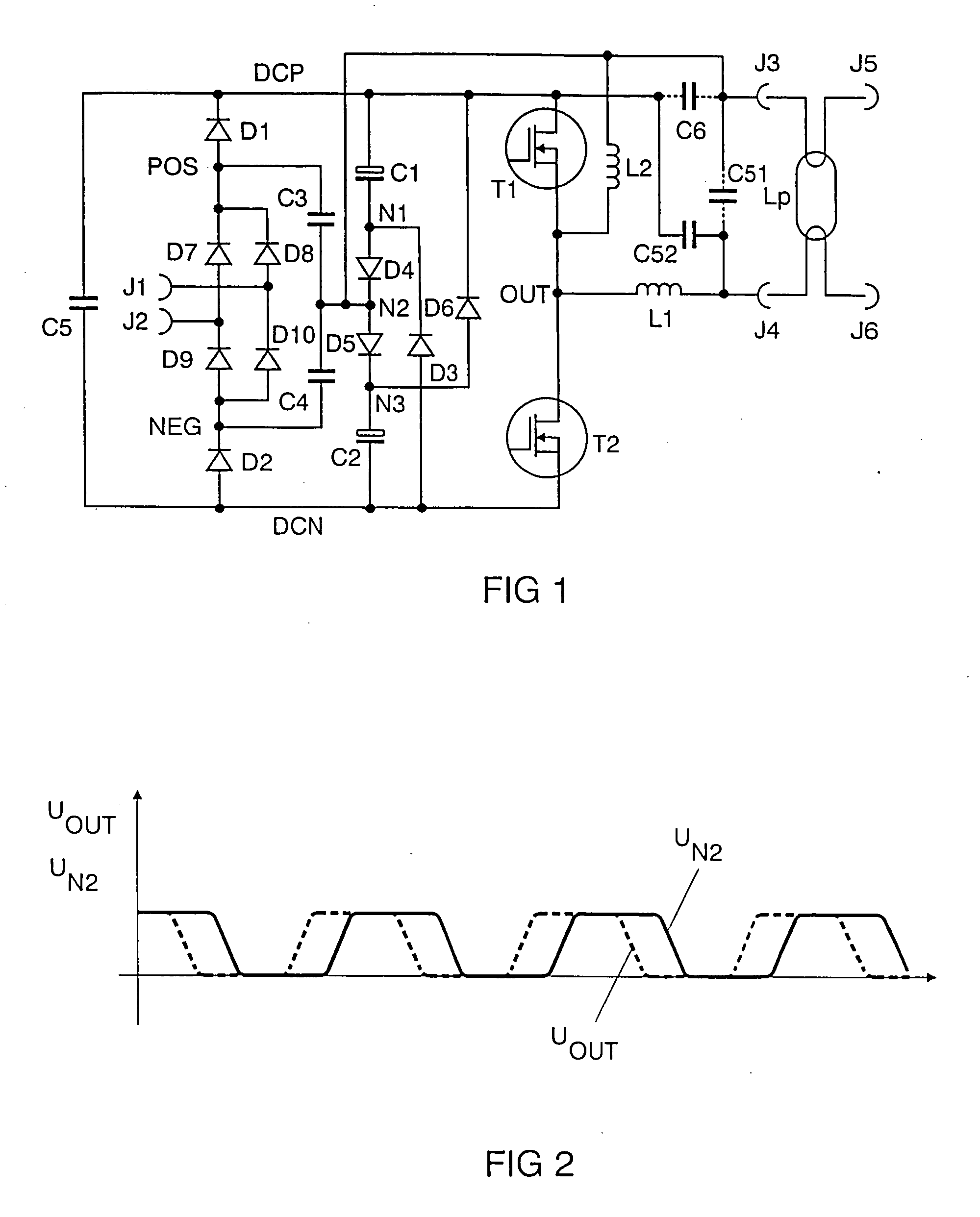
[0043]FIG. 1 shows an exemplary embodiment of the invention for a fluorescent lamp having electrode filaments. The connections J1 and J2 form the system voltage input. A system voltage can be connected to J1 and J2. J1 and J2 are connected to the input of a rectifier. Means for radio interference suppression may also be connected upstream of the rectifier.

[0044] In general, the rectifier comprises a known bridge circuit comprising the rectifier diodes D7, D8, D9 and D10 which make the rectified system voltage available at their positive rectifier output POS and their negative rectifier output NEG.

[0045] Owing to the charge pump, the rectifier diodes need to be able to be switched at a high frequency. It is also possible for slow rect...


PUM


Abstract

The present invention relates to a circuit arrangement for operating at least one light source. Cost-effective power factor correction of the system input is achieved by a combination of a charge pump and a valley-fill circuit. According to the invention, the voltage (UN2) produced by the charge pump is fed into the valley-fill circuit with a lag, for example by means of an inductor (L2).

Description

FIELD OF THE INVENTION [0001] The present invention relates to circuit arrangements for the purpose of supplying power to light sources from a power supply system which are suitable for correcting a system-side power factor. The abbreviation PFC will be used below for the expression power factor correction. [0002] A feed system voltage has a system frequency. The term “high-frequency” will be used below for frequencies which are substantially higher than the system frequency. BACKGROUND OF THE INVENTION [0003] The specification WO 02 / 47441 (Hu) has disclosed an abovementioned circuit arrangement. This specification has disclosed two PFC techniques: a charge pump (referred to as “single feedback” in the specification WO 02 / 47441 (Hu)) and a so-called valley-fill circuit (referred to as “double pump” in the specification WO 02 / 47441 (Hu)). In this case, the charge pump is connected upstream of the valley-fill circuit, when viewed from the system voltage. In addition, the charge pump a...

Claims


Application Information

Patent Timeline
IPC IPC(8): H05B41/24H05B41/16
CPCH02M1/4241Y02B70/126H05B41/28H05B45/355Y02B70/10H05B41/26
Inventor HECKMANN, MARKUS
Owner PATENT TREUHAND GESELLSCHAFT FUR ELECTRIC GLUEHLAMPEN MBH
Why Eureka
Try Eureka