
Method and apparatus for detecting a packet error in a wireless communications system with minimum overhead using tail bits in turbo code

a wireless communication system and tail bit technology, applied in the field of wireless communication, can solve the problem of relatively weak error detection capability of using these three bits alone for error detection purposes

Inactive Publication Date: 2006-03-16
LUCENT TECH INC +1
View PDF5 Cites 8 Cited by
  • Summary
  • Abstract
  • Description
  • Claims
  • Application Information

AI Technical Summary

Benefits of technology

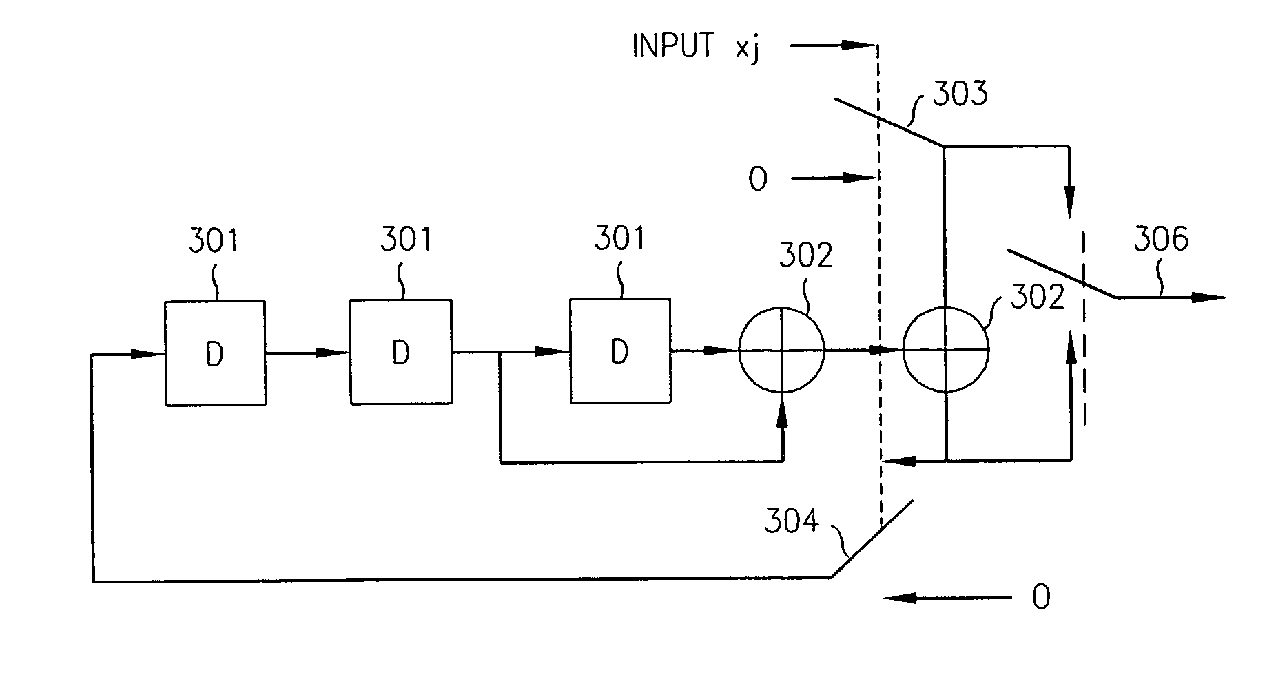
"The patent text describes a method for improving error detection in a wireless transmission system by using the tail bits generated by a turbo encoder. These tail bits are compared with CRC bits generated by a CRC encoder that uses the feedback polynomial g0(D) in the transfer function used by the turbo encoder. The resultant calculated tail bits are then compared with the systematic tail bits decoded by the turbo decoder. If a mismatch occurs, an error is indicated and the packet is marked as having failed. This method allows for error detection without needing to allocate and transmit additional bits for packet error detection purposes. The error detection capability is significantly better than using a three-bit CRC."

Problems solved by technology

Since only three tail bits are thus produced as output from each constituent encoder, the error detection capability afforded using these three bits alone is relatively weak for error detecting purposes.

Method used


Image

  • Method and apparatus for detecting a packet error in a wireless communications system with minimum overhead using tail bits in turbo code
  • Method and apparatus for detecting a packet error in a wireless communications system with minimum overhead using tail bits in turbo code
  • Method and apparatus for detecting a packet error in a wireless communications system with minimum overhead using tail bits in turbo code

Examples


Embodiment Construction

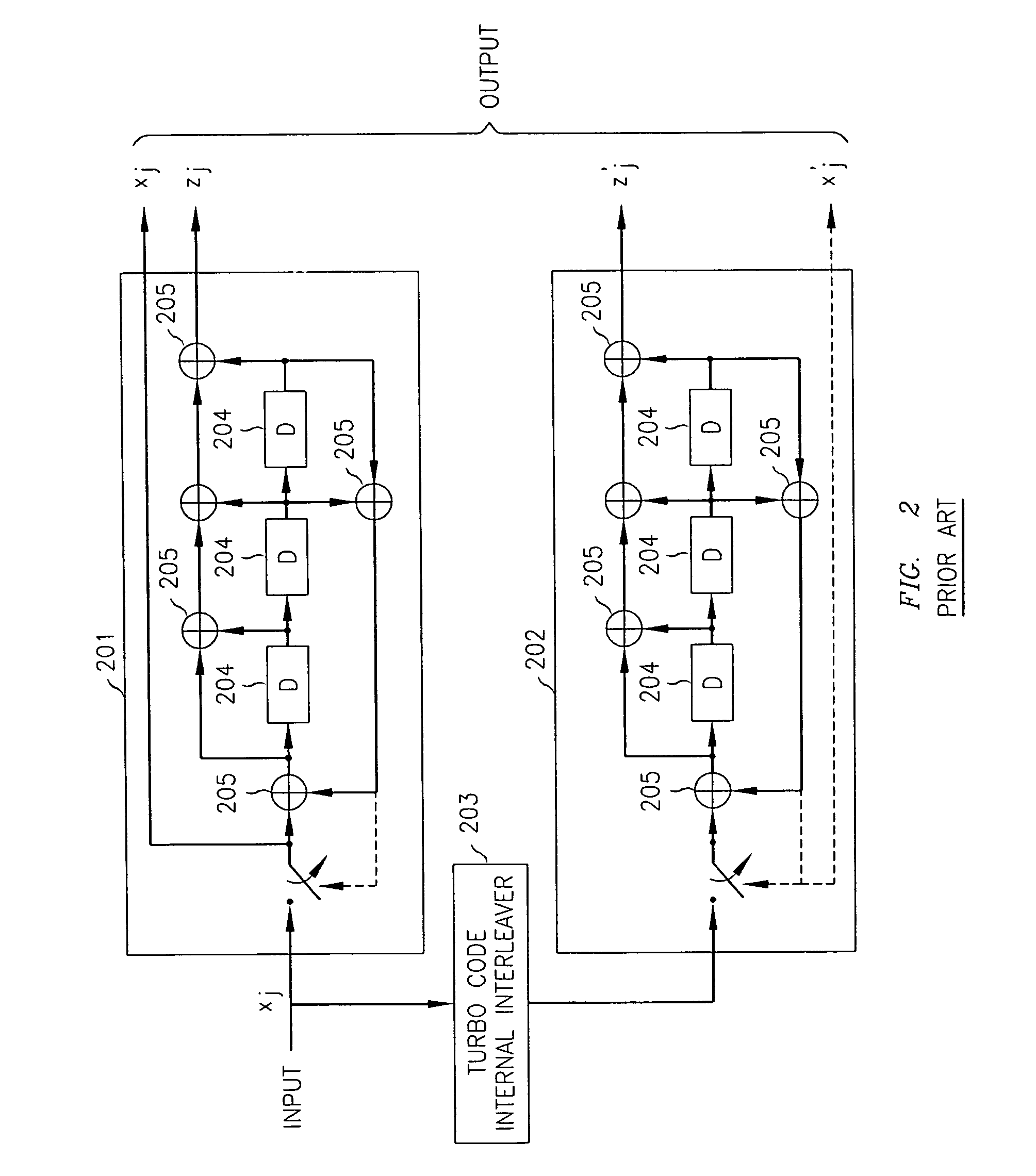
[0013] As afore noted, turbo coding is widely used in third generation wireless system such as 3GPP and 3GPP2, as well as in broadband fixed wireless IEEE802.16 systems and in satellite communications. Turbo coding is a well known in the art type of coding using a concatenation of two component codes (see, e.g., C. Berrou and A. Glavieux, “Near Optimum Error Correcting Coding and Decoding: Turbo-Codes,”IEEE Trans. Commun., vol 44, pp. 1261-1271, October 1996, and J. Hagenauer, “Iterative Decoding of Binary Block and Convolutional Codes,”IEEE Trans. Information Theory, vol. 42, pp. 429-445, March 1996). At the decoder, soft-decision decoding is performed on both received codes generating soft outputs (log-likelihood ratios). Specifically, decoding is split between the two codes by two decoders, one decoder exchanging the soft output with the other decoder after its own decoding, with the decoding being carried out multiple times, in a ping-pong manner, so that each iteration generate...


PUM


Abstract

The need for separate CRC bits is eliminated by taking advantage of what has been determined to be an embedded error detection capability of the tail bits generated by the constituent encoders of a turbo coder to perform error detection following turbo decoding. Specifically, it has been recognized that the tail bits are similar to CRC bits that would be generated by a CRC encoder that uses as its generating polynomial the feedback polynomial used by the turbo encoder. At the turbo decoder, after a final turbo decoding iteration cycle, a check is performed on the decoded systematic information bits by calculating the tail bits from the decoded information bits using that generating polynomial and bit-by-bit comparing the calculated tail bits with the systematic tail bits decoded by the turbo decoder. If a mismatch occurs at one or more bit positions, an error is indicated and the packet is marked as having failed. Advantageously, by using the tail bits for error checking, no additional bits need to be allocated and transmitted for packet error detection purposes.

Description

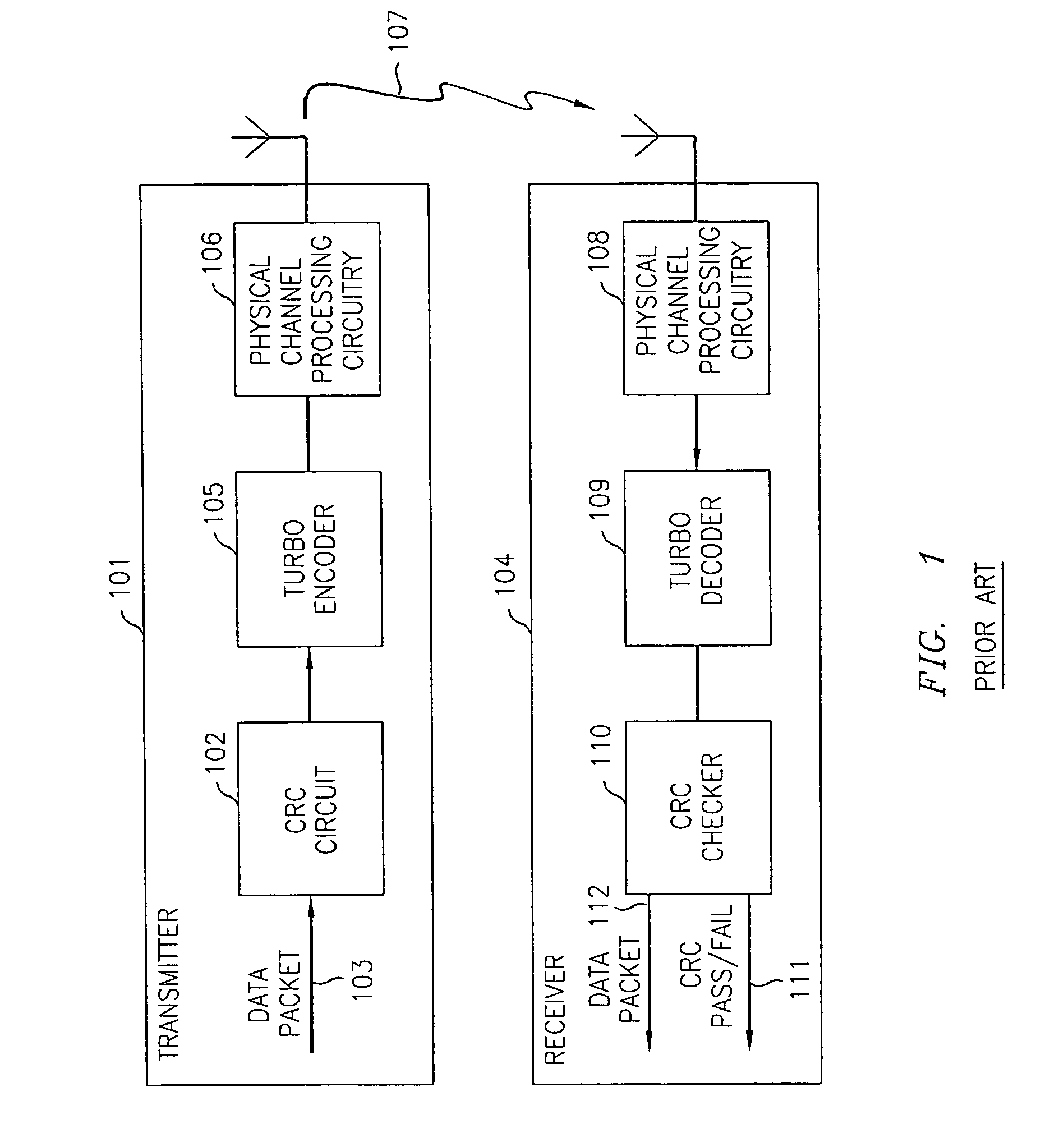
TECHNICAL FIELD [0001] This invention relates to wireless communications, and more particularly, to detecting a turbo-coded packet error at the receiver in a wireless communications system. BACKGROUND OF THE INVENTION [0002] In wireless communications systems, such as those operating in accordance with 3GPP2 CDMA2000-1x standards and 3GPP UMTS W-CDMA standards, a turbo code has been adopted for data transmission on both the uplink and downlink due to its superior error correcting capabilities. To detect the residue errors that cannot be corrected by the turbo decoder, Cyclic Redundancy Check (CRC) code bits are appended to the packet data before the encoder at the transmitter. A CRC check is then performed at the receiver on the decoded packet to determine whether a pass or fail results. [0003]FIG. 1 shows a high-level block diagram of wireless communications system that uses turbo encoding for error correction and CRC for error detecting. This block diagram is applicable to both 3G...

Claims


Application Information

Patent Timeline
Patent Type & Authority Applications(United States)
IPC IPC(8): H03M13/00
CPCH03M13/09
Inventor DOMINIQUE, FRANCISKONG, HONGWEI
Owner LUCENT TECH INC
Learn More