Soft contact lenses with stiffening rib features therein

a soft contact lens and rib technology, applied in the field of soft contact lenses with stiffening rib features there, can solve the problems of soft lenses having undesirable lens flexures, adverse effects on lens orientation, and dislocation of lenses,

Inactive Publication Date: 2006-03-16
MOLINARI JASON EMANUELE +6
View PDF4 Cites 91 Cited by
  • Summary
  • Abstract
  • Description
  • Claims
  • Application Information

AI Technical Summary

Benefits of technology

[0006] There is provided, in accordance with one aspect of the invention, a method for making a soft contact lens which is characterized by having an even distribution of pressure from the lens over the cornea of an eye. The method of the invention comprises a step of incorporating at least one stiffening rib feature in or near an area having localized and excessive pressure in a non-optical zone of a contact lens to provide localized stiffening effects on lens structure and to have a dynamic load causing the localized and excessive pressure to be spread over an enlarged area, thereby providing an even distribution of pressure from the lens over the cornea of an eye.
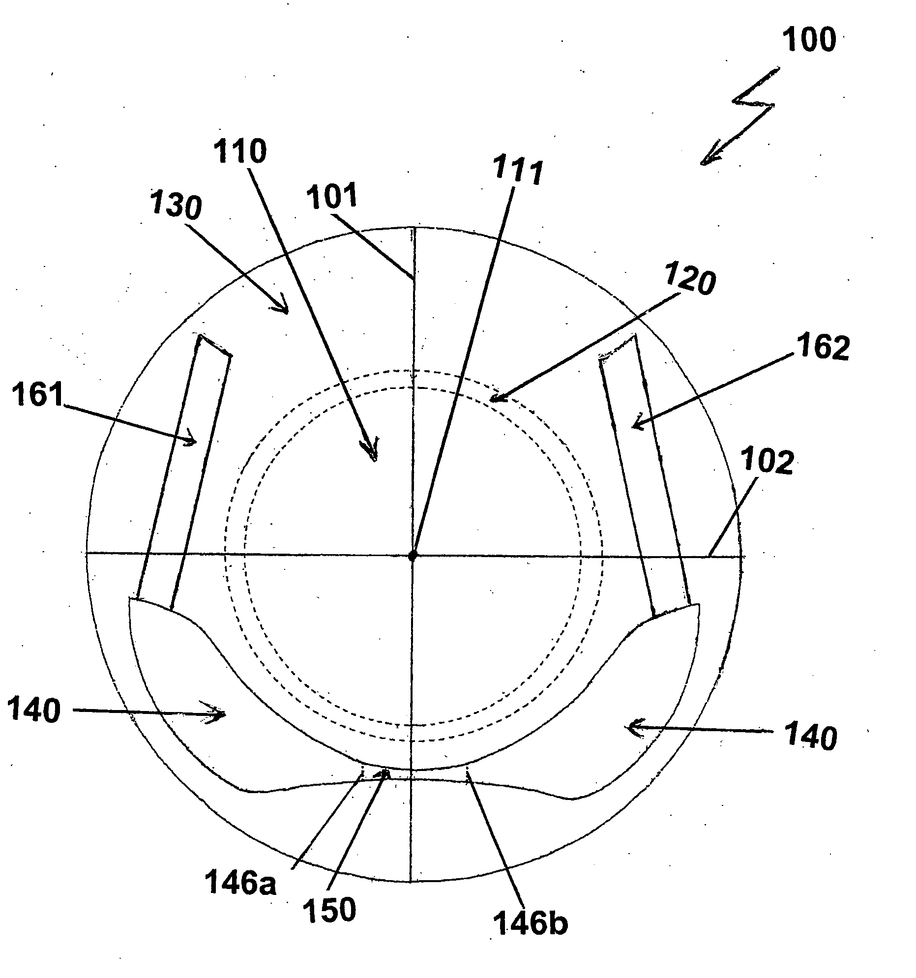
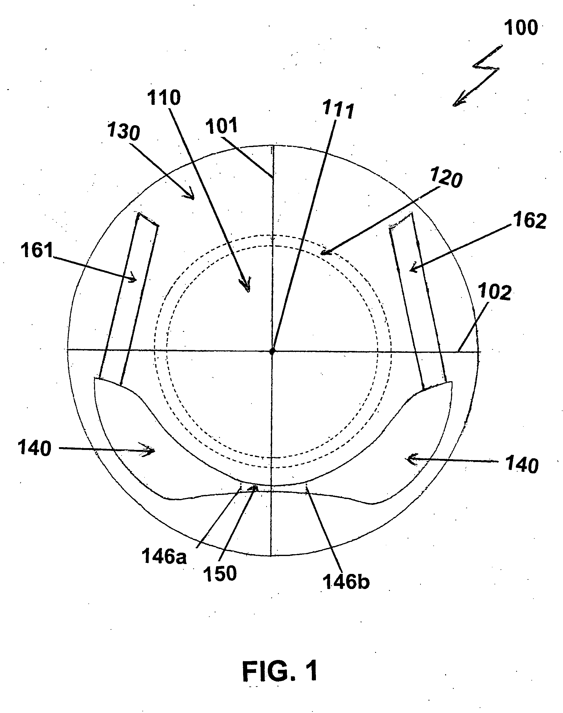
[0007] The invention, in another aspect, provides a method for a soft contact lens which is characterized by being able to maintain balance of forces for consistent and correct on eye lens orientation. The method of the invention comprises a step of incorporating at least one pair of stiffening rib features in a non-optical zone of a contact lens having a vertical meridian and a mirror symmetry relative to the vertical meridian plan, wherein each of the pair of stiffening rib features is arranged on either side of the vertical meridian plane to provide localized and directional stiffening effects on lens structure, wherein combination of the directions of the pair of stiffening rib features is parallel to the vertical meridian.
[0008] The invention, in a further aspect, provides a soft contact lens which is characterized by being able to maintain balance of forces for consistent and correct lens orientation on an eye during lens translation or eye lid movement. The contact lens of the invention comprises an anterior surface, an opposite posterior surface, a vertical meridian plane and at least one pair of stiffening rib features. The anterior surface has a mirror symmetry with respect to the vertical meridian plane, is continuous at least in first derivative, and includes a vertical meridian, a horizontal meridian, a central optical zone and a peripheral zone extending outwardly from the central optical zone to lens edge. The pair of stiffening rib features are located in the peripheral zone and on either side of the vertical meridian plane to provide localized and directional stiffening effects on lens structure, wherein combination of the directions of the pair of stiffening rib features is parallel to the vertical meridian.

Problems solved by technology

Soft contact lenses have alleviated some of the problems that patients have experienced in not being able to wear hard contact lenses (e.g., RGP lenses) or in not being able to wear them for sufficiently long periods of time, because of initial discomfort (i.e., immediately after lens insertion), relatively long period of adapting time (a week or two) required for a patient to become accustomed to them, and / or improper fit (lenses become dislodged and / or are very uncomfortable).
However, be cause of this pliability which permits the lenses to flex to conform more closely to the underlying corneal shape, a soft lens can have undesirable lens flexures under the influence of the eyelids and / or lens movement.
Such lens flexures may have adverse effects on the lens orientation stability (consistent and correct lens orientation) on eye and / or vertical translation of the optical zones of a translating bifocal soft contact lens across the pupil when the eye changes from primary (horizontal) gaze to a downward gaze.
In addition, some orientation stabilizing and / or translating features incorporated in a soft toric or translating bifocal contact lens may inadvertently change local mechanical properties of the lens structure so that pressure from the lens could not be evenly distributed over the cornea of an eye.
These features may impart unevenly localized dynamic loads onto certain areas of the lens and may generate excessive or localized pressure on the cornea.

Method used


Image

  • Soft contact lenses with stiffening rib features therein
  • Soft contact lenses with stiffening rib features therein

Examples


Embodiment Construction

[0011] Reference now will be made in detail to the embodiments of the invention. It will be apparent to those skilled in the art that various modifications and variations can be made in the present invention without departing from the scope or spirit of the invention. For instance, features illustrated or described as part of one embodiment, can be used on another embodiment to yield a still further embodiment. Thus, it is intended that the present invention cover such modifications and variations as come within the scope of the appended claims and their equivalents. Other objects, features and aspects of the present invention are disclosed in or are obvious from the following detailed description. It is to be understood by one of ordinary skill in the art that the present discussion is a description of exemplary embodiments only, and is not intended as limiting the broader aspects of the present invention.

[0012] Unless defined otherwise, all technical and scientific terms used her...


PUM


Abstract

The present invention is related to a method for designing and making a contact lens which comprises stiffening rib features that provide even distribution of pressure from the lens over the cornea of an eye and / or allows the lens structure to maintain balance of forces for consistent and correct lens orientation on an eye during lens translation or eye lid movement. The invention also provides a soft contact lens comprising stiffening rib features that provides localized directional reinforcements to the lens structure to evenly distribute pressure from the lens over the cornea of an eye and / or to maintain balance of forces for consistent and correct lens orientation on an eye during lens translation or eye lid movement.

Description

[0001] This application claims the benefit under 35 USC § 119(e) of U.S. provisional application No. 60 / 598,869 filed Aug. 4, 2004, incorporated by reference in its entirety.[0002] This invention is related to contact lenses. In particular, the present invention is related to a method for providing localized stiffness to a soft contact lens at a desired location while having minimal impact on overall softness of a soft contact lens, a method for reducing excessive and localized pressure on the cornea by incorporating a stiffening rib feature to spread a dynamic load causing the excessive and localized pressure over an enlarged lens portion, thereby providing substantially even distribution of pressure from the lens over the cornea of an eye, and a method for maintaining balance of forces for consistent and correct on-eye orientation of a soft contact lens during lens translation or eye lid movement. The invention further provides a contact lens comprising stiffening rib features tha...

Claims


Application Information

Patent Timeline
IPC IPC(8): G02C7/02
CPCG02C7/04G02C7/043G02C2202/08G02C2202/04G02C7/048
Inventor MOLINARI, JASON EMANUELEMORGAN, COURTNEY FLEMLINDACHER, JOSEPH MICHAELANDINO, RAFAEL VICTORFISHER, S. KAYSNOWDEN, TRACY J.ZHOU, JIAN
Owner MOLINARI JASON EMANUELE
Why Eureka
Try Eureka