Combustion-engined setting tool

a technology of combustion engine and setting tool, which is applied in the direction of manufacturing tools, machines/engines, nailing tools, etc., can solve the problems of increasing the weight of the tool, affecting the efficiency of the tool, and fraction of the required mechanical energy obtained from the combustion process, etc., and achieves the effect of high energy efficiency

Active Publication Date: 2006-03-16
HILTI AG
View PDF9 Cites 1 Cited by
  • Summary
  • Abstract
  • Description
  • Claims
  • Application Information

AI Technical Summary

Benefits of technology

[0012] Another object of the present invention is to provide a setting to

Problems solved by technology

With a laminar combustion, the combustion process and the resulting pressure increase take place so slow that only a fraction of the required mechanical energy can be obtained from the combustion process.
The drawback of the setting tool of the European Patent consist in complicated and costly electronics which actuates and controls the ventilator means and which also actuates ignition.
A further drawback consists in that several accumulators are needed, which increases the tool weight.
The drawback of the tool disclosed in DE 199 62 711 A1 consists in that the combustion process is se

Method used


Image

  • Combustion-engined setting tool
  • Combustion-engined setting tool
  • Combustion-engined setting tool

Examples


Embodiment Construction

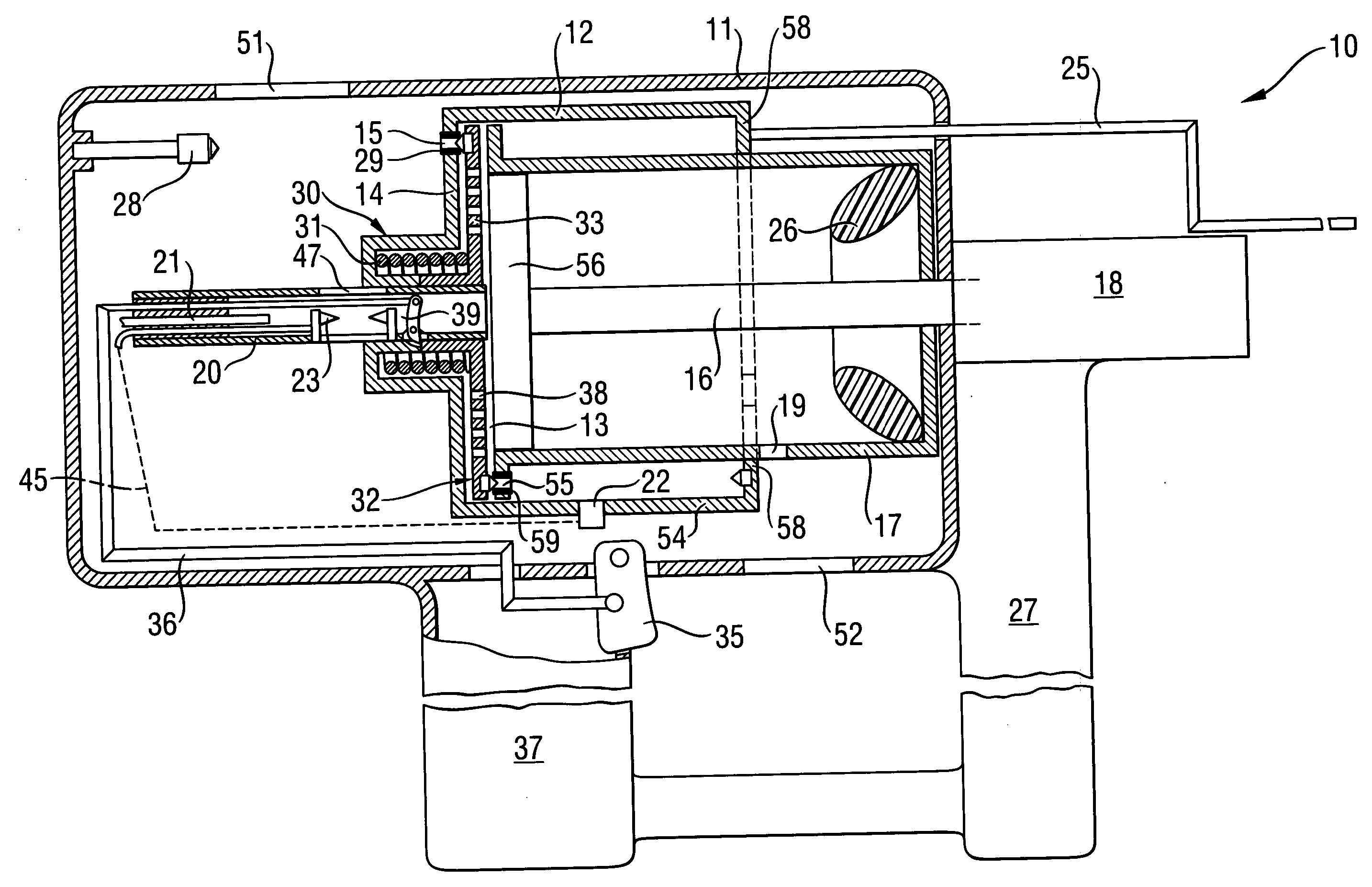
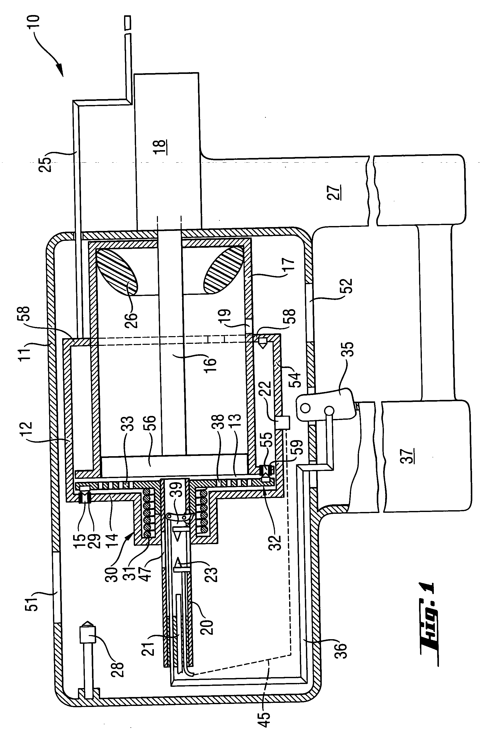
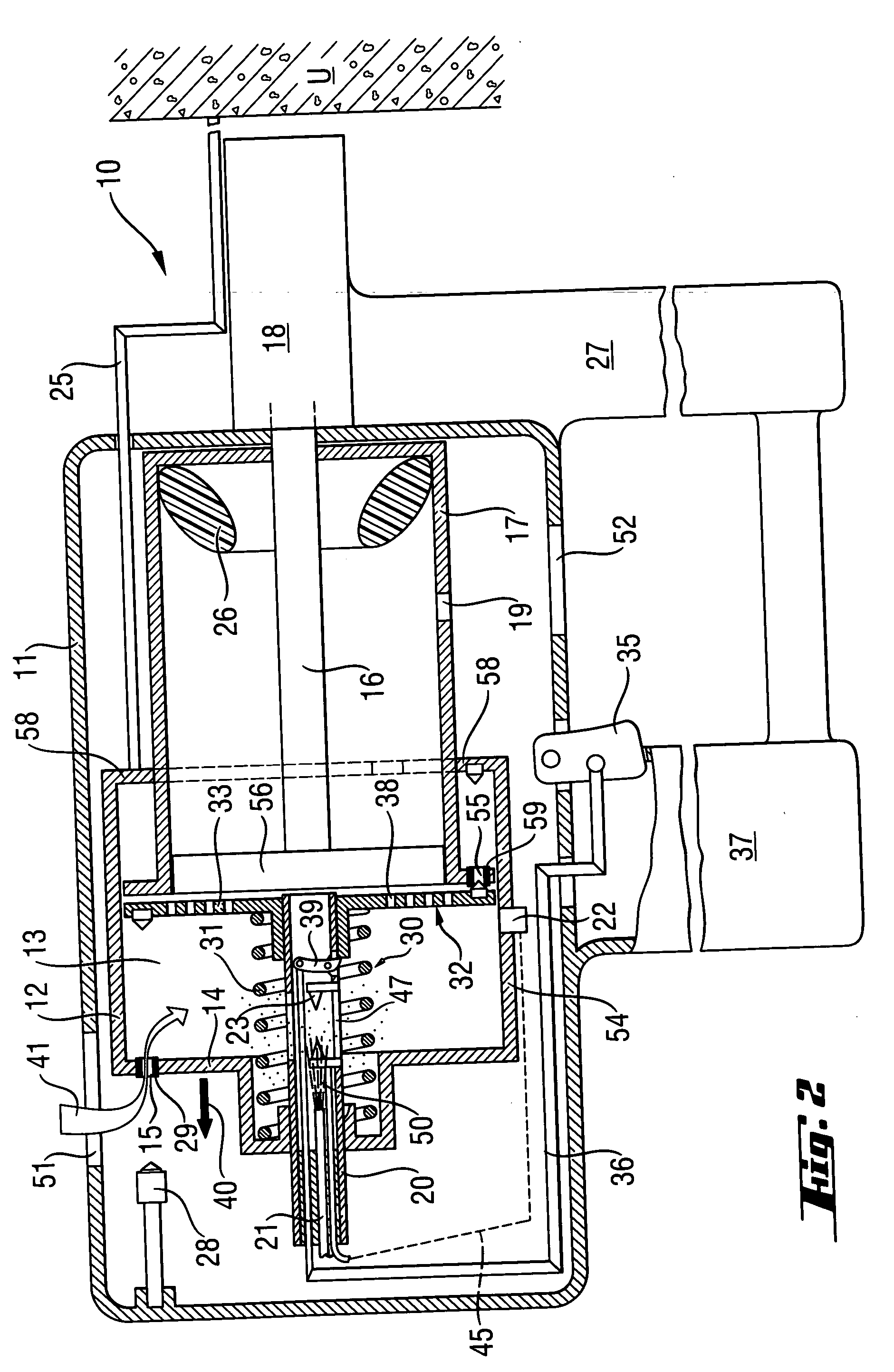
[0033] A setting tool 10 according to the present invention, which is shown in FIGS. 1-5, operates on a liquid or gaseous fluid.

[0034] The setting tool 10 has a housing 11 in which there is arranged a setting mechanism with which a fastening element such as a nail, a bolt or the like can be driven in a constructional component U (FIGS. 2-5) when the setting tool 10 is pressed against the constructional component U and is actuated.

[0035] The setting mechanism includes, among others, a combustion chamber casing 12 in which a combustion chamber 13 is expandable, a piston guide 17 in which a setting piston 16 is displaceably arranged, and a bolt guide 18 in which a fastening element can be displaced by setting direction end of the forward movable setting piston 16 and, thereby, be driven in a constructional component. The fastening element can, e.g., be stored in magazine 27 on the setting tool 10.

[0036] The combustion chamber 12 is displaceably arranged with respect to the piston gu...


PUM


Abstract

A combustion-engined setting tool for driving fastening elements in constructional components includes a member (32) arranged in the combustion chamber (13) for generating turbulence of an oxidant-fuel mixture filling the combustion chamber (13), an ignition unit (23) for igniting the oxidant-fuel mixture, a drive for at least temporarily driving the turbulence generating member (32), and a switch (22) for actuating the ignition unit (23) and actuated by the turbulence generating member (32).

Description

BACKGROUND OF THE INVENTION [0001] 1. Field of the Invention [0002] The present invention relates to a combustion-engined setting tool for driving fastening elements such as, e.g., nails, bolts, pins, in a constructional components and which includes a combustion chamber, means arranged in the combustion chamber for generating turbulence of an oxidant-fuel mixture filling the combustion chamber, an ignition unit for igniting the oxidant-fuel mixture, and drive means for a least temporarily driving the turbulence generating means. [0003] 2. Description of the Prior Art [0004] In the setting tools described above, a portion of the liquid gas or another vaporable fuel, which is mixed with an oxidant, e.g., environmental air, is combusted in the tool combustion chamber. In order to obtain as high as possible drive-in energy from the combustion process, it is important that the combustion of the gas or gas mixture takes place under turbulent flow conditions. Only a turbulent combustion p...

Claims


Application Information

Patent Timeline
IPC IPC(8): F02B71/00
CPCB25C1/08
Inventor SCHIESTL, ULRICHGSCHWEND, HANSWOLF, IWAN
Owner HILTI AG
Why Eureka
Try Eureka