
Shoulder pad for contact sports

a shoulder pad and contact technology, applied in the field of shoulder pads, can solve the problems of affecting the overall comfort of the shoulder pad, the range of motion of the side pad assembly is limited, etc., and achieve the effects of reducing both material and assembly costs, facilitating installation, and facilitating mobility

Active Publication Date: 2006-03-16
RIDDELL
View PDF20 Cites 21 Cited by
  • Summary
  • Abstract
  • Description
  • Claims
  • Application Information

AI Technical Summary

Benefits of technology

[0014] Compared to conventional shoulder pads, the present invention provides a number of advantages. The fastening assembly that secures the side pad assembly to the body arch member provides a greater amount of mobility for the side pad assembly with respect to the arch member. In addition, the fastening assembly comprises few parts, primarily the single band, and is easily installed on the shoulder pad thereby reducing both material and assembly costs. The raised segments of the arch member, the shoulder cap, and the epaulet form the distribution and energy attenuation system that distributes and generally reduces an impact force throughout the pad assembly. Regarding the integrated interior pad assembly, combining multiple pads into a single pad assembly provides for more efficient air management upon an impact to the shoulder pad. Furthermore, due to the integrated construction of the interior pad assembly, the shoulder pad is more comfortable for the participant to wear while playing the contact sport.

Problems solved by technology

Due to the rigid connection provided by the straps, the range of motion of the side pad assembly is limited and the overall comfort of the shoulder pad is affected.

Method used


Image

  • Shoulder pad for contact sports
  • Shoulder pad for contact sports
  • Shoulder pad for contact sports

Examples


Embodiment Construction

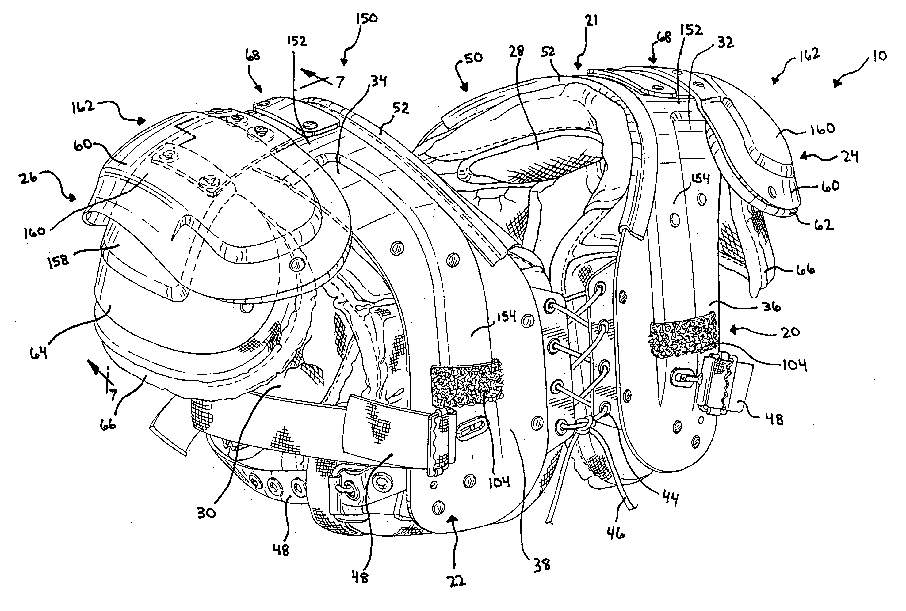
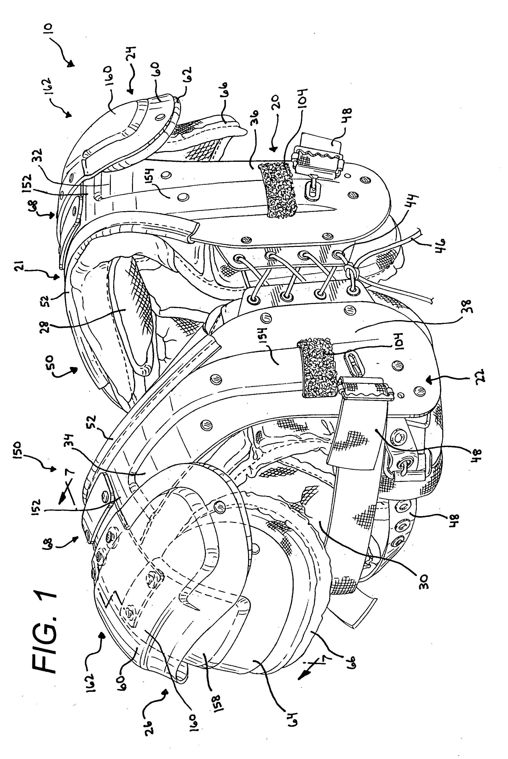
[0030] While this invention is susceptible of embodiments in many different forms, there is shown in the drawings and will herein be described in detail preferred embodiments of the invention with the understanding that the present disclosure is to be considered as an exemplification of the principles of the invention and is not intended to limit the broad aspect of the invention to the embodiments illustrated.

[0031] A shoulder pad assembly 10 is shown in FIGS. 1 and 4-7. The shoulder pad 10 is configured to be worn by a participant of a contact sport, such as football, hockey or lacrosse. The shoulder pad 10 includes a first or left body arch member 20, a second or right body arch member 22, a left side pad assembly 24 flexibly connected to the left body arch member 20, and a right side pad assembly 26 flexibly connected to the right body arch member 22. A central body 21 is defined by the left and right body arch members 20, 22 which are operably joined to form the central body 2...


PUM


Abstract

The present invention provides a shoulder pad for use in a contact sport, such as football, hockey or lacrosse. The shoulder pad includes a pair of arch members, each having an upper portion, a front portion depending from the upper portion, and a rear portion depending from the upper portion. The shoulder pad further includes at least one side pad assembly having an epaulet and a shoulder cap, wherein the shoulder cap overlies the wearer's shoulder region and the epaulet overlies both the arch member and the shoulder cap. The side pad assembly is operably secured to the body arch member by a fastening assembly that includes a flexible single band. Unlike conventional designs, the single band secures both the epaulet and the shoulder cap to the upper portion of the arch member. The shoulder pad further includes a pair of interior pad assemblies wherein each interior pad assembly is removably connected to an arch member. The interior pad assembly is an integrated unit formed from a front pad, an intermediate pad, and a rear pad joined together to form distinct air management chambers.

Description

CROSS-REFERENCE TO RELATED APPLICATIONS [0001] This application claims priority from U.S. Provisional Patent Application No. 60 / 609,489, filed Sep. 13, 2004, which application is incorporated herein by reference and made a part hereof.FEDERALLY SPONSORED RESEARCH OR DEVELOPMENT [0002] Not applicable. TECHNICAL FIELD [0003] The invention relates to a shoulder pad assembly worn by a player in a contact sport, such as football, lacrosse or hockey. The shoulder pad has a novel fastening assembly for connection of a side pad assembly, an energy attenuation system for dissipating an impact force, and a unique integrated interior pad assembly. BACKGROUND OF THE INVENTION [0004] In most contact sports, the players are required to wear an assortment of protective gear, including shoulder pads, to reduce the occurrence of injury. For example, conventional football shoulder pads are bilaterally symmetrical and are generally comprised of right and left body arch members which extend over the sh...

Claims


Application Information

Patent Timeline
Patent Type & Authority Applications(United States)
IPC IPC(8): A41D27/26
CPCA63B71/12A63B2243/007A63B2071/1208
Inventor IDE, THAD M.OBY, CHRISTOPHER D.
Owner RIDDELL
Learn More