
Porous coatings for drug release from medical devices

Inactive Publication Date: 2006-03-09
MEDTRONIC INC
View PDF13 Cites 105 Cited by
  • Summary
  • Abstract
  • Description
  • Claims
  • Application Information

AI Technical Summary

Benefits of technology

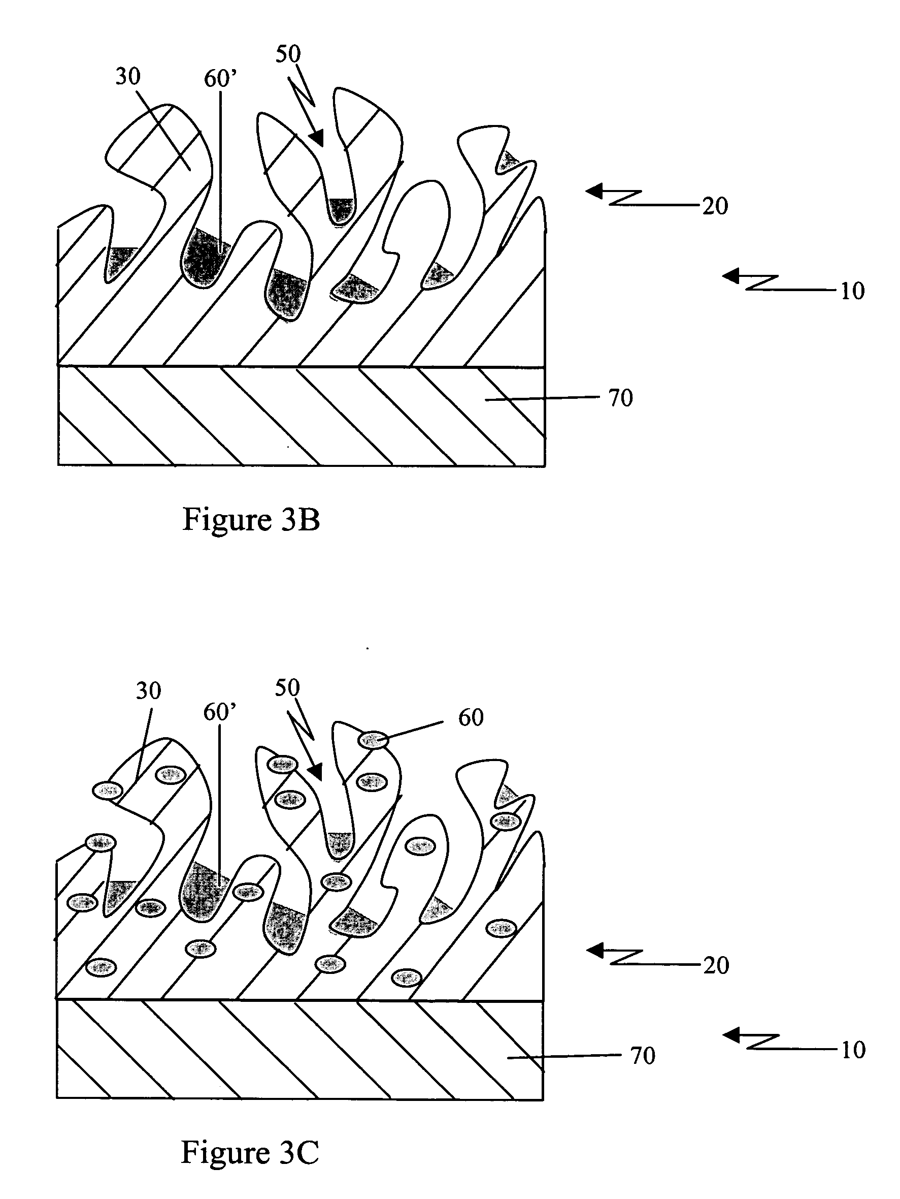
[0008] Such a device may provide one or more advantages over existing non-vascular medical devices. For example, pores in the polymeric layer increase the rate at which therapeutic agent may be released from the matrix. Further, loading therapeutic agent in the pores, as opposed to just the matrix, can increase the total amount of therapeutic agent that may be loaded into the device. In addition, therapeutic agent loaded into the pores will be quickly released from the device after implantation. Loading therapeutic agent into or on the surface layer and / or one or more intermediate layers allows for additional loading capacity, as well as finer control of the release profile of therapeutic agent from the device. Another advantage of a polymeric layer comprising pores is the ability of tissue to integrate with the pores after implantation. Thus, release of therapeutic agent may become more effective as less drug is removed into interstitial fluids, surrounding tissue, etc. These and other advantages will become evident to one of skill in the art upon reading the disclosure herein.

Problems solved by technology

Implantation of medical devices, such as pacemakers, neurostimulators, implanted drug pumps, leads, catheters, etc, has been associated with adverse consequences, such as formation of scar tissue surrounding the implant, infection due to bacteria introduced during implantation, and tissue proliferation in blood vessels after a stent implantation.
In other cases, systemic delivery has been ineffective due to, e.g., pharmacokinetic or pharmacodynamic characteristics of the drug, the location of the implanted device, or side effects of the drug.
However, many IMDs are made from metals or from polymers that are inherently incompatible with the desired drug.
However, problems exist with current loading technology.
For example, it can difficult to load large quantities of drugs or to adjust release rates when conventional biomaterials, such as silicone rubber and polyurethane, are used as a matrix for drug loading.
Localized intravascular delivery of drugs, such as that achievable by drug-eluting intravascular devices, presents unique challenges.
Difficulties associated with drug-eluting extravascular implantable medical devices have not been adequately addressed.

Method used


Image

  • Porous coatings for drug release from medical devices
  • Porous coatings for drug release from medical devices
  • Porous coatings for drug release from medical devices

Examples


example 1

[0074] Porous polymer retains more drug and increases initial burst release of drug release relative to non-porous polymer

Methods

[0075] Silicone tubing from a Medtronic Model 8831 catheter, having nominal dimensions of 0.050″ OD and 0.021″ ID, was cut into approximately 1 inch pieces. After cleaning in tetrahydrofuran (THF), tubing was dip coated with two solutions containing 15 g of either RTV 1137 or RTV 2000 (NuSil Technology, Carpinteria, Calif.) together with sodium bicarbonate salt (15 g) and THF solvent (45 g). After proper drying and curing, tubing was placed in deionized water to extract the sodium bicarbonate salt.

[0076] Lumens of original (non-porous) and porous samples were filled with RTV-1137 and cured to prevent drug loading into tubing lumens. Samples with blocked lumens were placed in 1% of dexamethasone acetate solution in acetone for 30 seconds followed by drying overnight at 37° C. Drug loaded samples were placed in 5 ml of PBS buffer and incubated under stir...


PUM

PropertyMeasurementUnit
Sizeaaaaaaaaaa
Sizeaaaaaaaaaa
Metallic bondaaaaaaaaaa

Abstract

Extravascular implantable medical devices are described. The devices include a polymeric layer comprising a polymeric matrix and pores. Therapeutic agent is loaded in the matrix, in the pores, or in the matrix and the pores. The devices include a structural surface layer. Additional therapeutic agent may be loaded in or on the surface layer. The devices may also include one or more intermediate layer, into or onto which additional therapeutic agent may be loaded.

Description

FIELD [0001] The present disclosure relates to medical devices coated with porous polymers as vehicles for drug delivery. BACKGROUND [0002] Implantation of medical devices, such as pacemakers, neurostimulators, implanted drug pumps, leads, catheters, etc, has been associated with adverse consequences, such as formation of scar tissue surrounding the implant, infection due to bacteria introduced during implantation, and tissue proliferation in blood vessels after a stent implantation. Attempts to prevent or control such adverse reactions have included administration of drugs, completely separate from the intended primary therapy of the implanted medical device. In some cases, systemically administered drugs, e.g. orally, intravenously, or intramuscularly administered drugs, have proven effective in treating complications due to medical device implantation. In other cases, systemic delivery has been ineffective due to, e.g., pharmacokinetic or pharmacodynamic characteristics of the dr...

Claims


Application Information

Patent Timeline
IPC IPC(8): A61F2/00
CPCA61F2/02A61F2250/0068A61L27/34A61L27/54A61L27/56A61L29/085A61N1/30A61L29/16A61L31/10A61L31/146A61L31/16A61L2300/602A61L2300/61A61L29/146
Inventor HERUTH, KENNETH T.KOULLICK, EDOUARDLENT, MARK S.
Owner MEDTRONIC INC
Learn More