
Dark box apparatus for fluoroscopy, fluoroscopy system, and fluoroscopy method

Inactive Publication Date: 2006-03-09
OLYMPUS CORP
View PDF2 Cites 11 Cited by
  • Summary
  • Abstract
  • Description
  • Claims
  • Application Information

AI Technical Summary

Benefits of technology

[0010] The present invention has been conceived in light of these circumstances, and it is an object of the present invention to provide a dark box apparatus for fluoroscopy, a fluoroscopy system, and a fluoroscopy method for eliminating noise in a fluorescence image acquired during fluoroscopy to present a clear fluorescence image and for checking the relative positional relationship between the fluoroscopy unit and the specimen even while fluoroscopy is in progress.

Problems solved by technology

However, since fluorescence generated by a specimen is very weak, it is difficult to acquire a clear fluorescence image due to external noise if fluoroscopy is performed in the presence of extraneous light.
If fluoroscopy is to be performed in a darkroom such that a specimen is first positioned with respect to the microscope apparatus under extraneous light and then the specimen is illuminated with excitation light with all extraneous light blocked to detect fluorescence emitted from the specimen, unsuccessful positioning of the specimen, such as a shift of the specimen from the desired examination position, may occur.
This may cause the objective lens of the microscope apparatus to interfere with the specimen, possibly damaging the objective lens or the specimen.
In addition, repeating the procedure of introducing extraneous light for positioning and then blocking the extraneous light again for examination is time-consuming and annoying.

Method used


Image

  • Dark box apparatus for fluoroscopy, fluoroscopy system, and fluoroscopy method
  • Dark box apparatus for fluoroscopy, fluoroscopy system, and fluoroscopy method
  • Dark box apparatus for fluoroscopy, fluoroscopy system, and fluoroscopy method

Examples


first embodiment

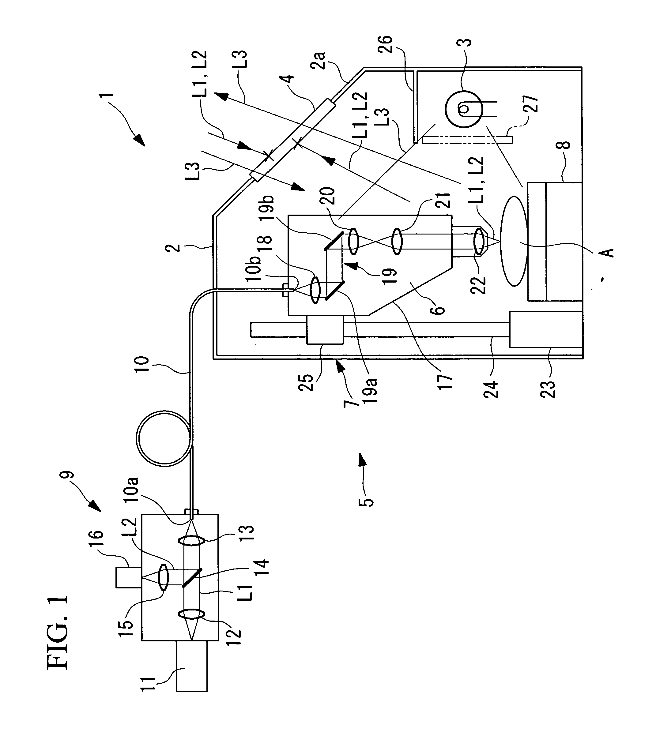
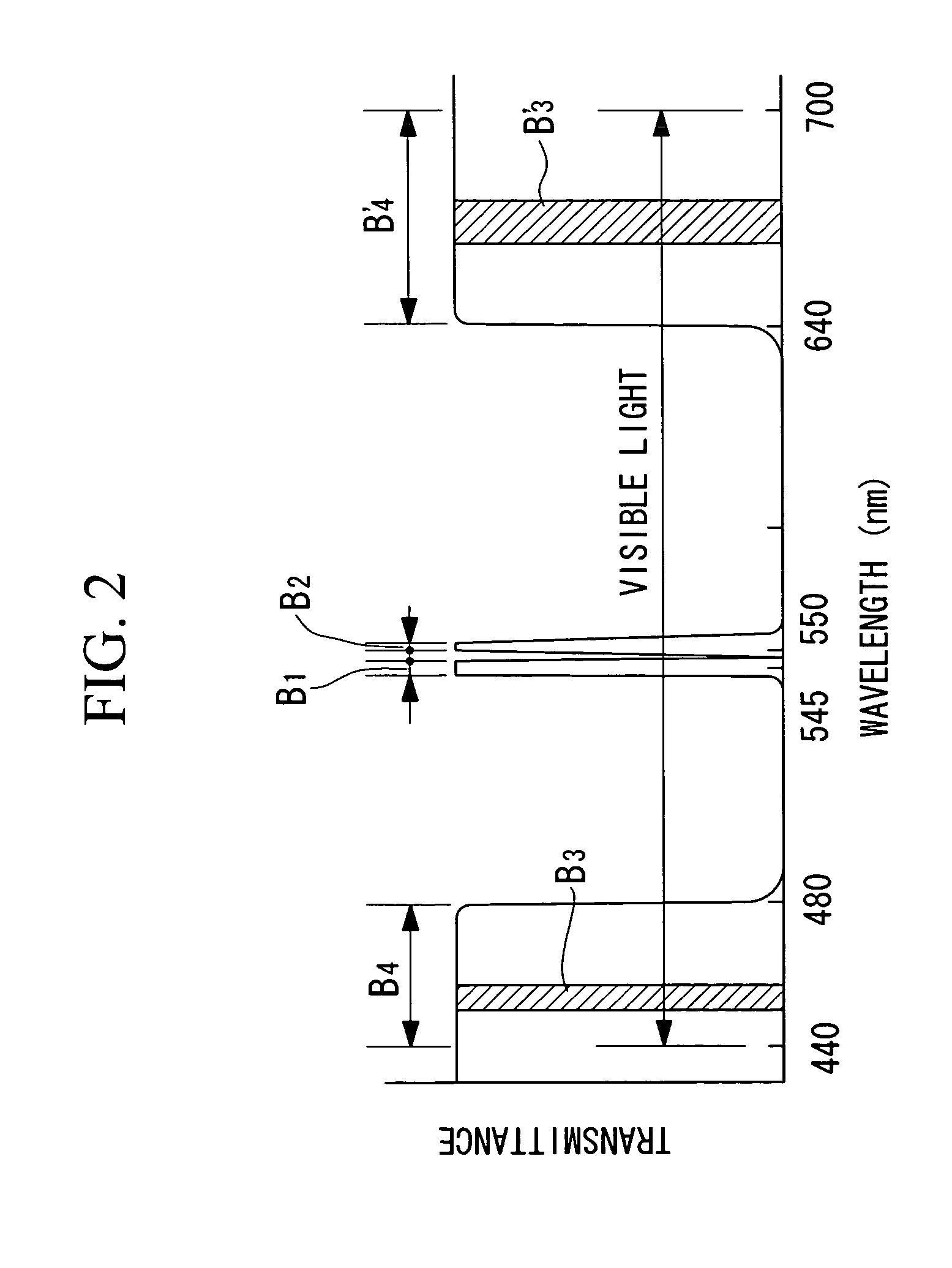
[0043] A dark box apparatus for fluoroscopy 1 according to the present invention will now be described with reference to FIGS. 1 and 2.

[0044] Referring to FIG. 1, the dark box apparatus for fluoroscopy 1 according to this embodiment includes a dark-box main body 2; an illumination light source 3 arranged in the dark-box main body 2; and an observation window 4 arranged in a wall surface 2a of the dark-box main body 2.

[0045] The above-described dark-box main body 2 is a box member composed of a material blocking light of all wavelengths, and is large enough to completely contain an examination head 6 of a fluoroscopy unit 5, to be described below; a raising-and-lowering mechanism 7 for raising and lowering the examination head 6; a specimen A; and a stage 8 holding the specimen A for moving the specimen A two-dimensionally in the horizontal direction or tilting the specimen A.

[0046] As shown in FIG. 1, the fluoroscopy unit 5 includes an optical unit 9; the examination head 6; and a...

second embodiment

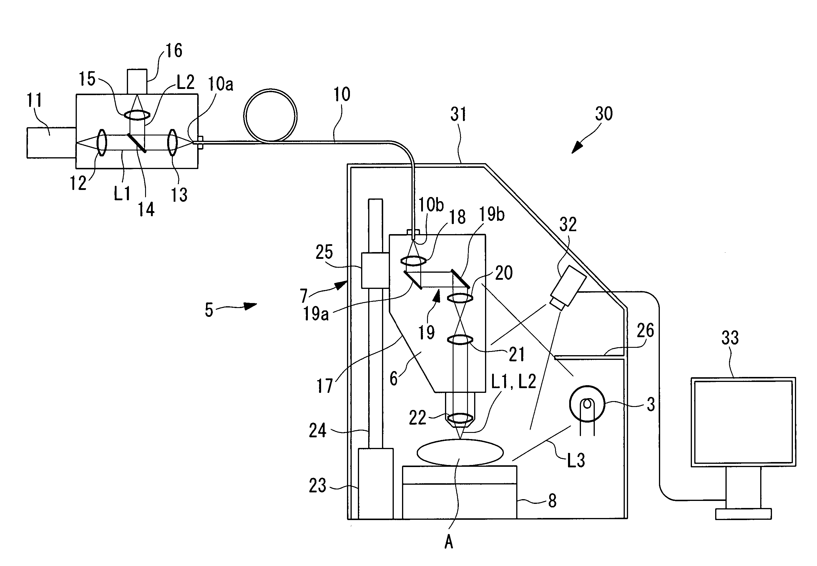
[0073] A dark box apparatus for fluoroscopy 30 according to the present invention will now be described with reference to FIG. 3.

[0074] The same components in this embodiment as those used in the dark box apparatus 1 according to the first embodiment shown in FIG. 1 are denoted by the same reference numerals, and thus will not be described.

[0075] Referring to FIG. 3, the dark box apparatus for fluoroscopy 30 according to this embodiment includes a dark-box main body 31 in place of the dark-box main body 2 of the dark box apparatus for fluoroscopy 1 according to the first embodiment. The dark-box main body 31 is not provided with the observation window 4 in the dark-box main body 2 to completely block extraneous light. Instead, a camera (photography unit) 32 is provided in the dark-box main body 31 and a monitor 33 is provided outside the dark-box main body 31.

[0076] The camera 32 has a field of view large enough to allow both the objective lens 22 of the fluoroscopy unit 5 and the...

third embodiment

[0082] A fluoroscopy system 40 according to the present invention will now be described with reference to FIG. 5.

[0083] The same components in this embodiment as those used in the dark box apparatuses 1 and 30 according to the first and second embodiments are denoted by the same reference numerals, and thus will not be described.

[0084] Referring to FIG. 5, a fluoroscopy system 40 according to this embodiment includes the above-described fluoroscopy unit 5 and a dark box apparatus for fluoroscopy 41. As shown in FIG. 5, the dark box apparatus for fluoroscopy 41 is provided on a dark-box main body 42 such that a door 43 can be opened and closed with a hinge 44. The dark-box main body 42 is provided with an open / closed sensor 46 that can detect a detection member 45 on the door 43 when the door 43 is closed.

[0085] Furthermore, an excitation-light control unit 47 is connected to the open / closed sensor 46. When the door 43 is opened, the open state of the door 43 is detected by the exc...


PUM


Abstract

Noise in a fluorescence image acquired during fluoroscopy is eliminated to present a clear fluorescence image, and the relative positional relationship between the fluoroscopy unit and the specimen can be recognized even while fluoroscopy is in progress. A dark box apparatus for fluoroscopy includes: a dark-box main body enclosing a specimen and a fluoroscopy unit for illuminating the specimen with excitation light with a first spectral band and for detecting fluorescence with a second spectral band generated by the specimen; an illumination light source disposed in the dark-box main body to emit light with a third spectral band different from the first spectral band and the second spectral band; and an observation window disposed in the dark-box main body, the observation window being capable of transmitting light with a fourth spectral band which includes at least part of the third spectral band and does not include the first spectral band and the second spectral band.

Description

BACKGROUND OF THE INVENTION [0001] 1. Field of the Invention [0002] The present invention relates to dark box apparatuses for fluoroscopy, fluoroscopy systems, and fluoroscopy methods. [0003] This application is based on Japanese Patent Applications No. 2004-257240, the contents of which are incorporated herein by reference. [0004] 2. Description of Related Art [0005] As a technique for non-invasively examining the interior of a specimen, some known confocal microscopes or multiphoton-excitation microscopes employ a fluoroscopy method for illuminating a specimen with excitation light, such as a laser beam, to examine fluorescence generated by the specimen. [0006] However, since fluorescence generated by a specimen is very weak, it is difficult to acquire a clear fluorescence image due to external noise if fluoroscopy is performed in the presence of extraneous light. For this reason, if fluoroscopy is to be performed in a darkroom, a specimen is first positioned with respect to the m...

Claims


Application Information

Patent Timeline
IPC IPC(8): G01N21/64
CPCG01N21/6458G01N21/6456
Inventor TSUYUKI, KEIOSA, KAZUHIKONAGASAWA, NOBUYUKI
Owner OLYMPUS CORP
Learn More