Ultraviolet rays emitter

Inactive Publication Date: 2006-03-09
SEIKO EPSON CORP
View PDF13 Cites 27 Cited by
  • Summary
  • Abstract
  • Description
  • Claims
  • Application Information

AI Technical Summary

Benefits of technology

[0018] Therefore, the invention has an object to solve the problems and to provide an ultraviolet rays emitter using a semiconductor light emitting element capable of preventing a thermal damage from being given to a recording medium as a light source for emitting ultraviolet rays, in which an ink of an ultraviolet curing type which is adhered onto the recording medium can be cured quickly irrespective of a adhering thickness thereof and the ultraviolet absorbing function of an ultraviolet absorbing substance in the ink.

Problems solved by technology

Therefore, there is a problem in that the infrared light in the continuous spectrum gives a thermal damage to the recording medium.
There is a problem in that the structure of a device is complicated and a cost is increased if a band-pass filter is provided in order to remove a hazardous infrared light.
The ultraviolet lamp greatly consumes power.
Therefore, there is a problem in that the energy saving of the ultraviolet rays emitter is hard to perform.
In addition, the ultraviolet lamp itself is large.
For this reason, there is also a problem in that it is hard to reduce the size and weight of a device model.
For example, there is a problem in that a print processing speed in an ink jet printer is hindered from being enhanced.
Consequently, the effect of curing the ink is reduced to half, and furthermore, an irradiation for a long time is required.
For this reason, actually, it is hard to maintain sufficient ultraviolet irradiation intensity in a wavelength region in which the absorption wavelengths of various ultraviolet absorbing substances are avoided.
However, there is a problem in that energy is low, resulting in an increase in a time required for curing the ink.
For this reason, there is a problem in that stable curing cannot be obtained.
However, a long time is required for the curing.
As a result, there is a problem in that the curing treatment is delayed.

Method used


Image

  • Ultraviolet rays emitter
  • Ultraviolet rays emitter
  • Ultraviolet rays emitter

Examples


Embodiment Construction

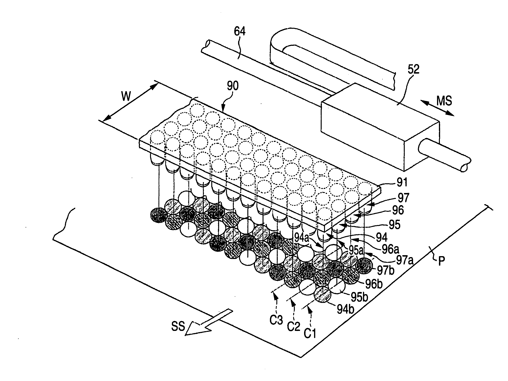
[0086] A suitable embodiment of an ultraviolet rays emitter according to the invention will be described below in detail with reference to the drawings.

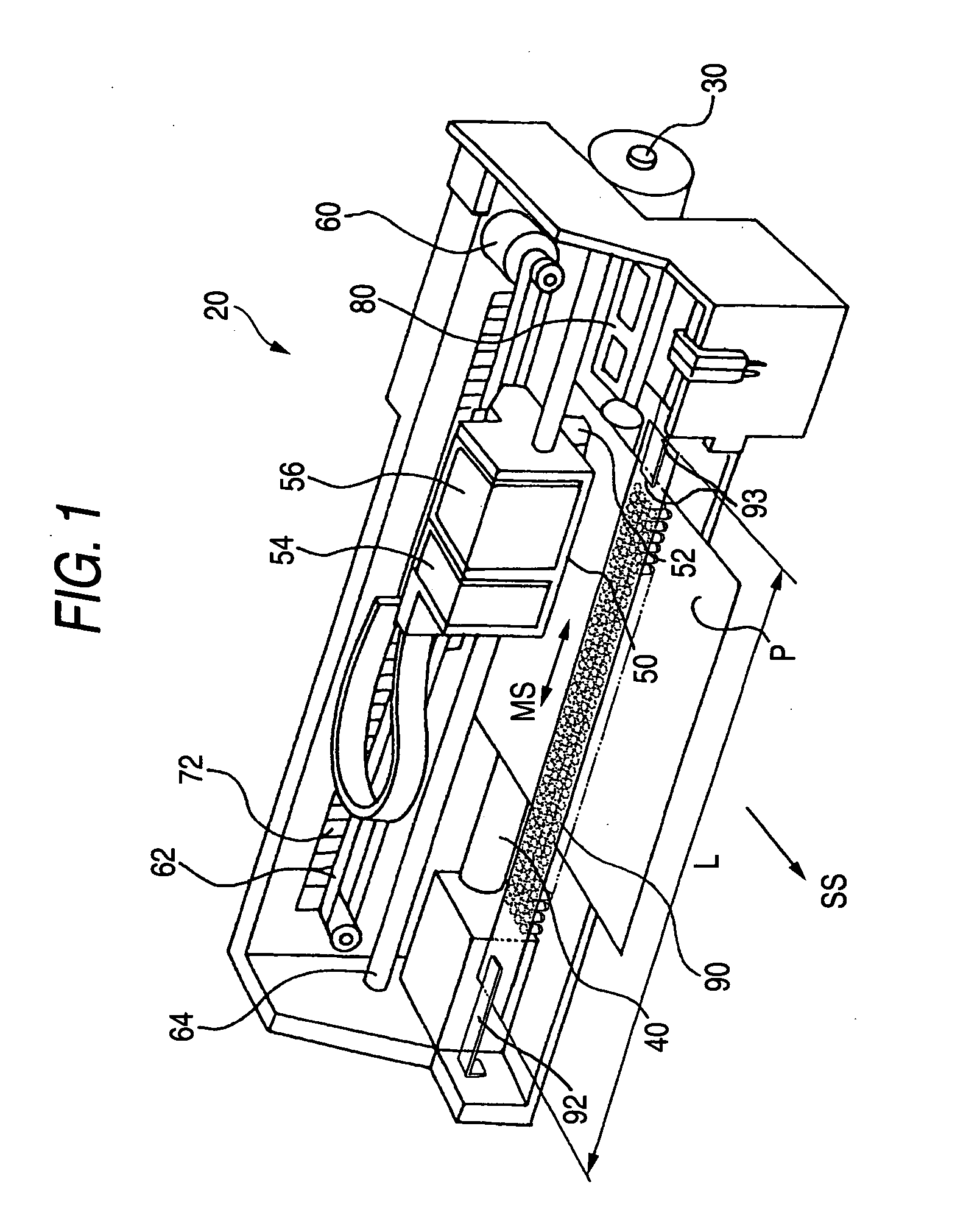
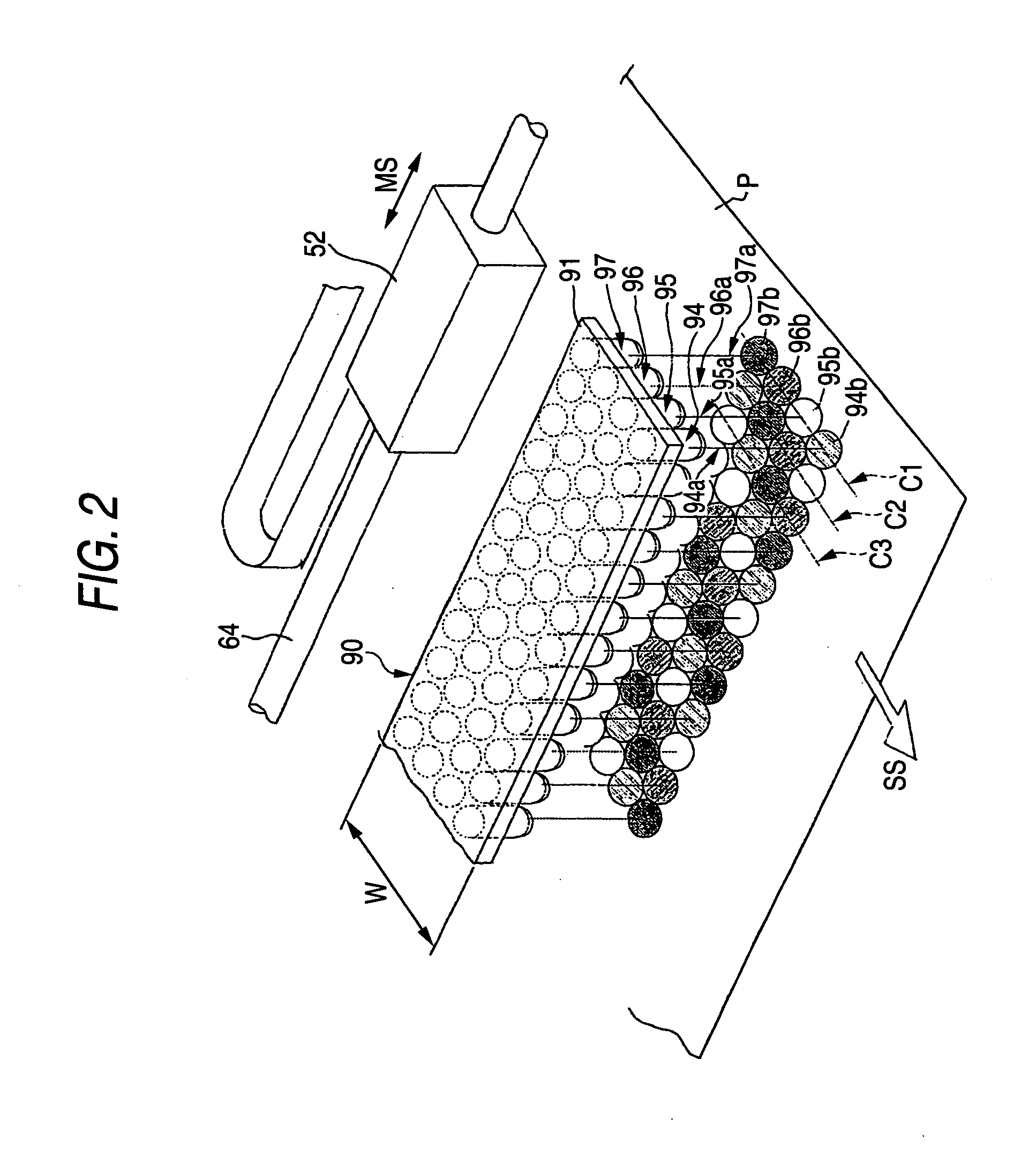
[0087]FIG. 1 is a schematic perspective view showing a main structure according to an embodiment of an ink jet printer 20 mounting an ultraviolet rays emitter in accordance with a first example of the invention. The first example will be described below.

[0088] The printer 20 comprises a paper feed motor 30 for feeding a print paper P to be a recording medium in a sub scanning direction SS, a platen 40, a print head 52 to be a recording head for causing an ink of an ultraviolet curing type to have a very small particle size and ejecting and adhering the same ink to the print paper P, a carriage 50 mounting the print head 52, a carriage motor 60 for moving the carriage 50 in a main scanning direction MS, and an ultraviolet rays emitter 90 for irradiating ultraviolet rays on an ink adhering surface of the print paper P to which the in...


PUM

PropertyMeasurementUnit
Wavelengthaaaaaaaaaa

Abstract

An ultraviolet rays emitter for irradiating ultraviolet rays on an ink of an ultraviolet curing type which is adhered onto a recording medium includes a plurality of semiconductor light emitting elements for emitting ultraviolet rays and a support member for mutually supporting these semiconductor light emitting elements in a matrix with optical axes thereof in almost parallel, and the row or column of the semiconductor light emitting element on the support member is set to have a structure in which two kinds of semiconductor light emitting elements having different wavelength ranges or more are arranged properly in order. Alternatively, an ultraviolet rays emitter according to another example is set to have a structure in which a plurality of semiconductor light emitting elements is mutually supported with a support member in a positional relationship in which the optical axes of the respective elements are mutually inclined in such a manner that the irradiation regions of ultraviolet rays emitted from the semiconductor light emitting elements are overlapped on a recording medium.

Description

BACKGROUND OF THE INVENTION [0001] The present invention relates to an ultraviolet rays emitter for emitting ultraviolet rays on an ink of an ultraviolet curing type which is adhered onto a recording medium, and more particularly to an improvement for implementing a quick curing treatment for the ink of the ultraviolet curing type which is adhered onto the recording medium without giving a thermal damage to the recording medium. [0002] The ink of the ultraviolet curing type is different from ordinary water-based and oil-based inks in that quick curing is carried out and stable printing quality can be maintained without the influence of the physical properties of a recording medium (for example, a print paper) such as an ink permeability if the ink of the violet curing type is adhered onto the recording medium and an ultraviolet ray is then irradiated in a proper amount. [0003] In an ink jet printer using the ink of the ultraviolet curing type, it is necessary to provide an ultraviol...

Claims


Application Information

Patent Timeline
IPC IPC(8): B41J2/01
CPCB41J11/002B41J11/00214
Inventor NAKANO, KEITAROOYANAGI, TAKASHI
Owner SEIKO EPSON CORP
Why Eureka
Try Eureka