
Method for frame rate conversion

a frame rate and conversion method technology, applied in the field of methods, can solve the problems of frame tearing, method cannot completely avoid the problem of frame tearing, and the practice is prone to frame tearing, so as to achieve a better time point for switching

Active Publication Date: 2006-03-09
REALTEK SEMICON CORP
View PDF1 Cites 17 Cited by
  • Summary
  • Abstract
  • Description
  • Claims
  • Application Information

AI Technical Summary

Benefits of technology

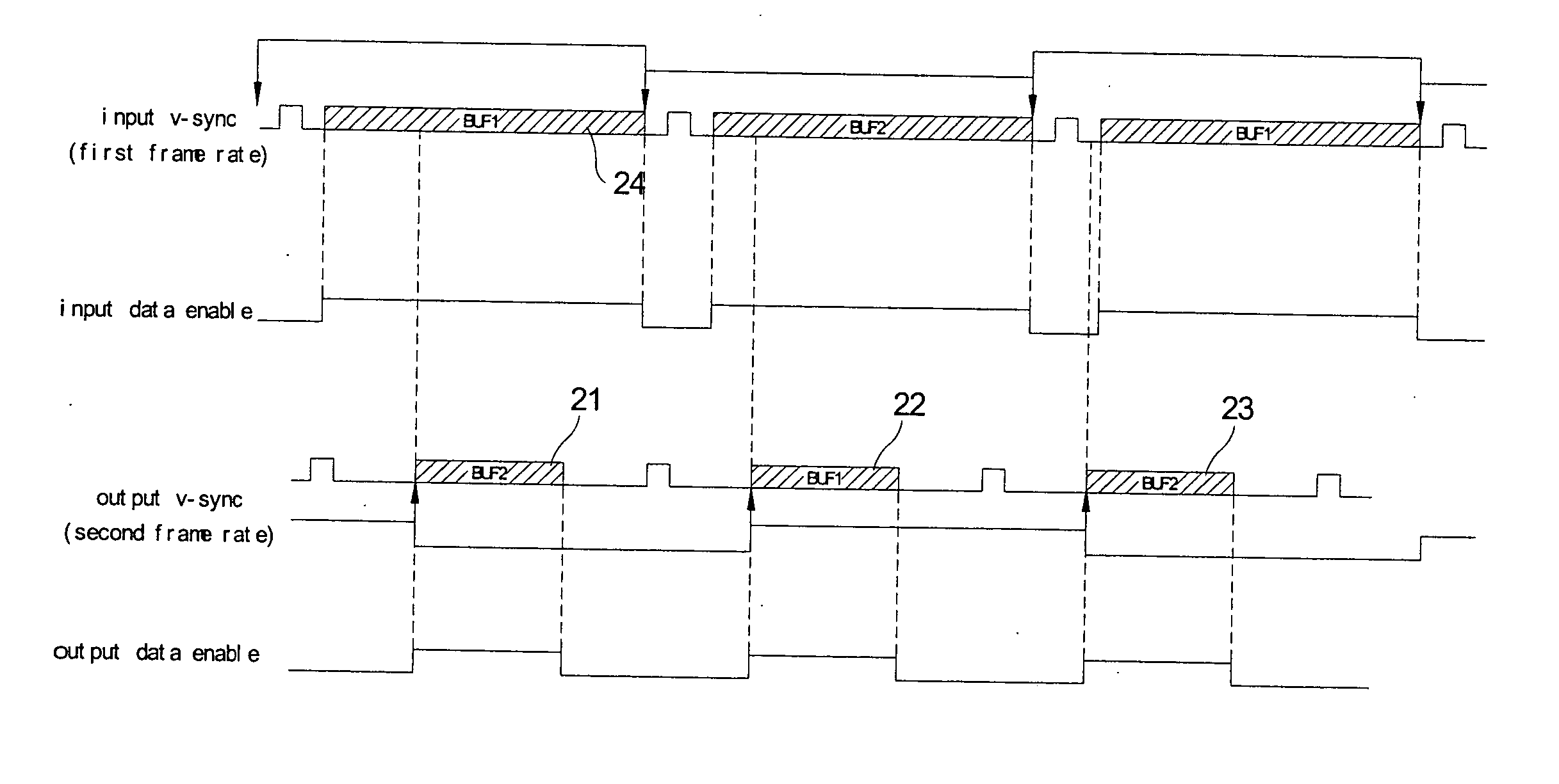
[0008] It is therefore one of objectives of this invention to provide a method for frame rate conversion in order to provide a better time point for switching and selecting the buffer to avoid the above mentioned problem.

Problems solved by technology

However, this practice is prone to frame tearing, that is, the top and bottom parts of an actual displayed frame contain image data belonged to different frames.
The frame tearing is due to the limited space of the frame buffer.
However, this conventional method cannot totally avoid the problem of frame tearing.

Method used


Image

  • Method for frame rate conversion
  • Method for frame rate conversion
  • Method for frame rate conversion

Examples


Embodiment Construction

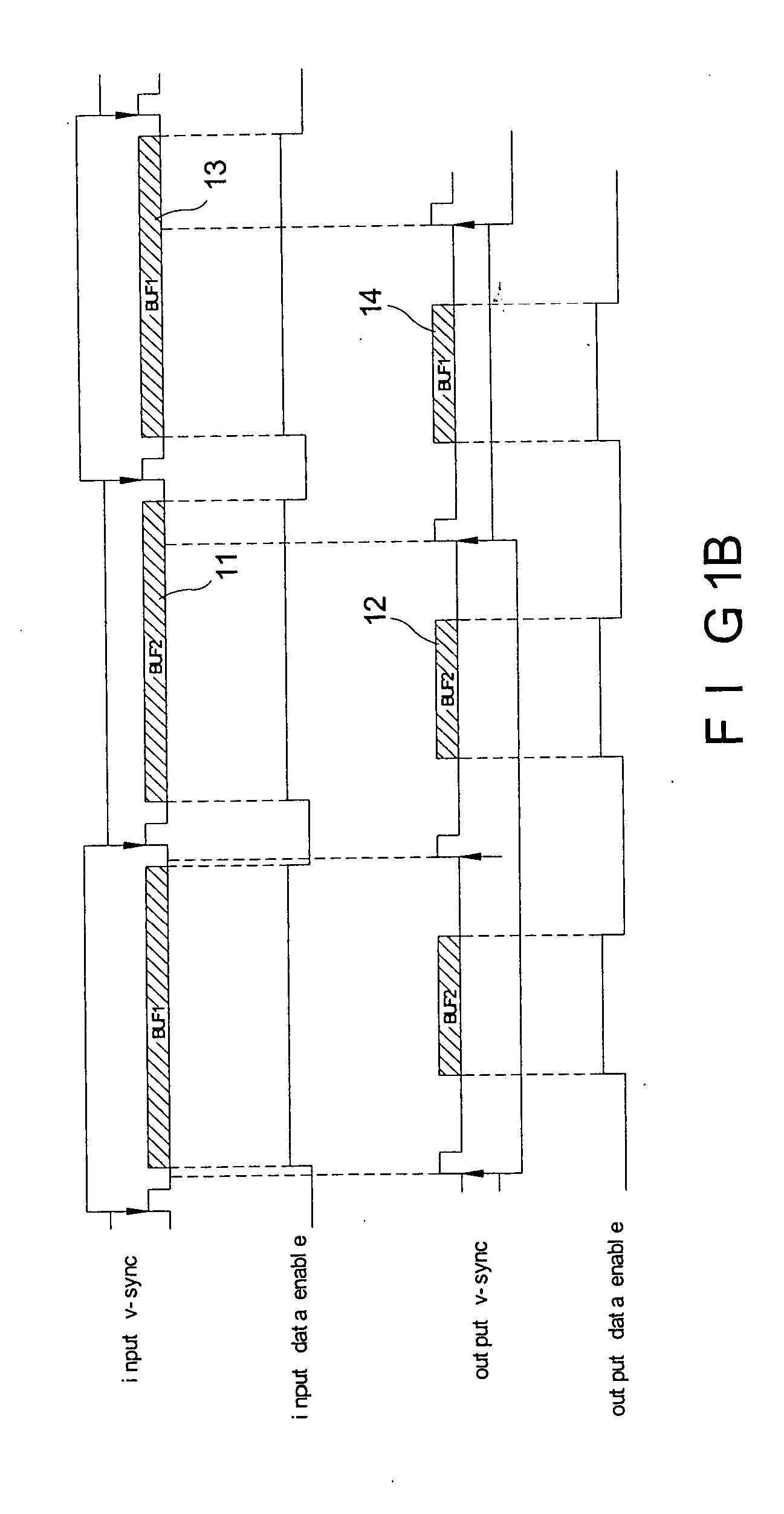
[0014] In an embodiment of this invention, the buffer-switching time point lies in between the ending of the data enable signal and the starting of the v-sync signal, and the buffer-selecting time point lies in between the ending of the v-sync signal and the starting of the data enable signal. This embodiment performs the conversion between two different frame rates by utilizing two buffers alternatively to access frame data.

[0015] As mentioned later, with the design of the buffer-switching time point (for the slow frame rate, this lies in between the ending of the data enable signal and the starting of the v-sync signal) and the buffer-selecting time point (for the fast frame rate, this lies in between the ending of the v-sync signal and the starting of the data enable signal), the frame tearing problem can be effectively avoided. For the rest of this specification, the two different frame rates will be referred to as the first frame rate and the second frame rate, with the assump...


PUM


Abstract

A method for converting a frame rate of a video signal comprising a data enable signal by means of a first buffer and a second buffer is disclosed. The method comprises: alternatively accessing the first buffer and the second buffer according to a first frame rate; determining an accessing time point of the first and the second buffers according to the data enable signal; and accessing the buffer, which is one of the first and the second buffers and not accessed at the accessing time point, according to a second frame rate, wherein the second frame rate is faster than the first frame rate.

Description

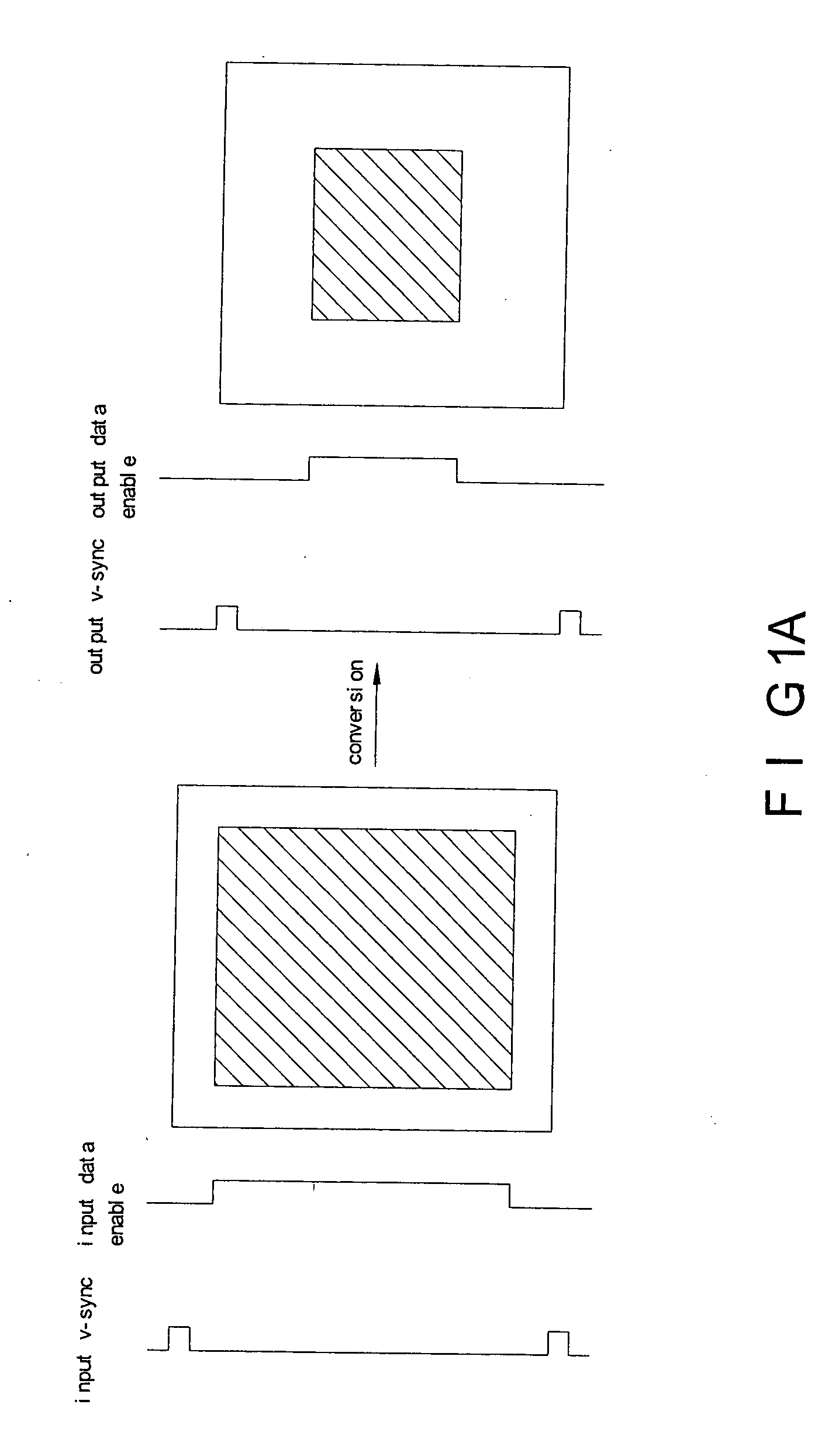
BACKGROUND OF THE INVENTION [0001] (a). Field of the Invention [0002] This invention is related to the field of frame rate conversion, and especially to the method for frame rate conversion using two buffers. [0003] (b). Description of the Prior Arts [0004] For a display device, such as a CRT or LCD display, frame rate conversion (FRC) is needed when the input frame rate is different from the output frame rate that the display supports, or when two different sources of input frame are to be outputted jointly in one output frame rate. The frame rate, in this aspect, is defined as the number of frames being processed in a unit time. For example, in a commonly used personal computer system, frame rate conversion is needed because the input frame rate from the display card (e.g. VGA card) to the display might be different from the refresh frequency of the display device (i.e. the output frame rate of the display device, which is usually set at 60 Hz). FIG. 1A is a diagram illustrating f...

Claims


Application Information

Patent Timeline
IPC IPC(8): G09G5/397H04N1/40
CPCH04N7/0127H04N7/0105
Inventor GONG, JIN SHENGCHOU, YU PINTONG, SHIU RONG
Owner REALTEK SEMICON CORP
Learn More