
Operation control apparatus for compressor and method thereof

a technology of operation control apparatus and compressor, which is applied in the field of compressors, can solve the problems of increasing the production cost of the compressor b>12/b>

Inactive Publication Date: 2006-03-09
LG ELECTRONICS INC
View PDF9 Cites 34 Cited by
  • Summary
  • Abstract
  • Description
  • Claims
  • Application Information

AI Technical Summary

Benefits of technology

[0009] Therefore, it is an object of the present invention to provide an operation control apparatus for a compressor and its method capable of protecting the compressor from being over-loaded through a current control device instead of a PTC thermistor and an OLP.
[0010] It is another object of the present invention to provide an operation control apparatus for a compressor and its method capable of reducing a production cost of the compressor by protecting the compressor from being over-loaded through a current control device instead of a PTC thermistor and an OLP.

Problems solved by technology

However, in the reciprocating compressor used for a refrigerator according to the conventional art, a stroke increases slowly so that an over current is not generated rapidly when the compressor initially starts.
Also, a production cost of the compressor 12 increases by installing the OLP 11 at the compressor 12.

Method used


Image

  • Operation control apparatus for compressor and method thereof
  • Operation control apparatus for compressor and method thereof
  • Operation control apparatus for compressor and method thereof

Examples


first embodiment

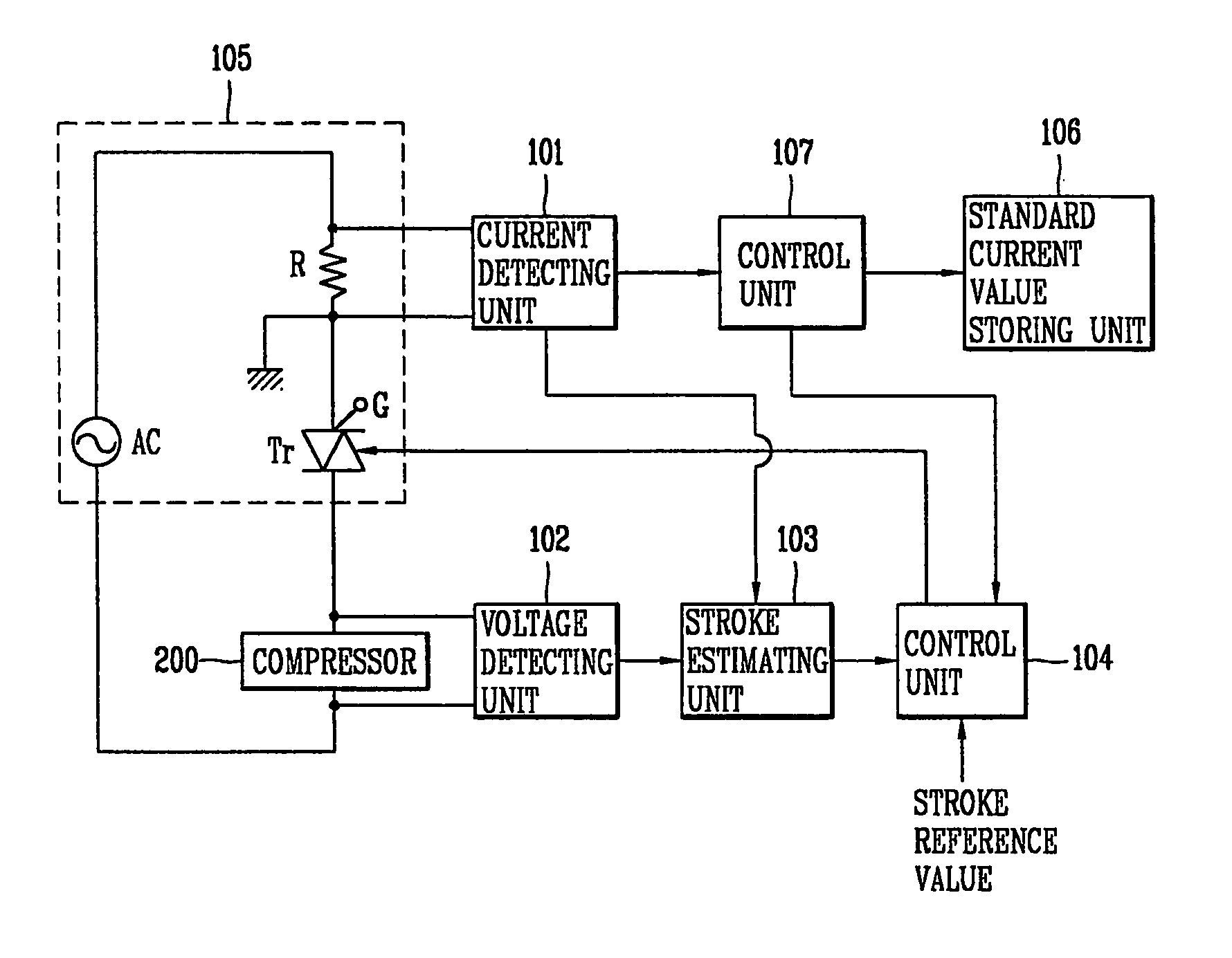
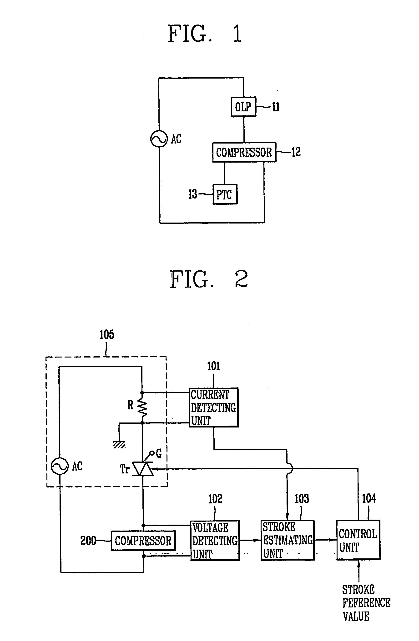
[0021]FIG. 2 is a block diagram showing a configuration of the operation control apparatus for the reciprocating compressor according to the present invention. That is, the amount of currents applied to the compressor 200 is controlled through the current control device (triac, Tr) installed at the compressor 200 without using the OLP (Over Load Protector) and the PTC thermistor. Also, when the compressor initially starts, a stroke of the compressor is estimated to slowly increase the stroke of the compressor, and varies the stroke of the compressor by turning on / off the current control device (Tr) at a certain period on the basis of the estimated stroke.

[0022] As shown therein, the operation control apparatus for the reciprocating compressor includes: a voltage detecting unit 102 for detecting a voltage applied to an interior motor (not shown) of the reciprocating compressor 200 when the reciprocating compressor is operated; a current detecting unit 101 for detecting a current appl...

second embodiment

[0028] Hereinafter, a configuration of an operation control apparatus for the reciprocating compressor according to the present invention will now be described in detail with reference to FIG. 4.

[0029]FIG. 4 is a block diagram showing the configuration of the operation control apparatus for the reciprocating compressor according to the second embodiment of the present invention. That is, in the operation control apparatus for the reciprocating compressor according to the second embodiment of the present invention, a current control device (Tr) instead of the OLP and the PTC thermistor is installed at the compressor 200, and the amount of currents applied to the interior motor of the compressor 200 is controlled through the current control device (Tr). Also, in the operation control apparatus for the reciprocating compressor according to the second embodiment of the present invention, in order to protect the compressor 200 from an overcurrent generated when the compressor 200 initial...


PUM


Abstract

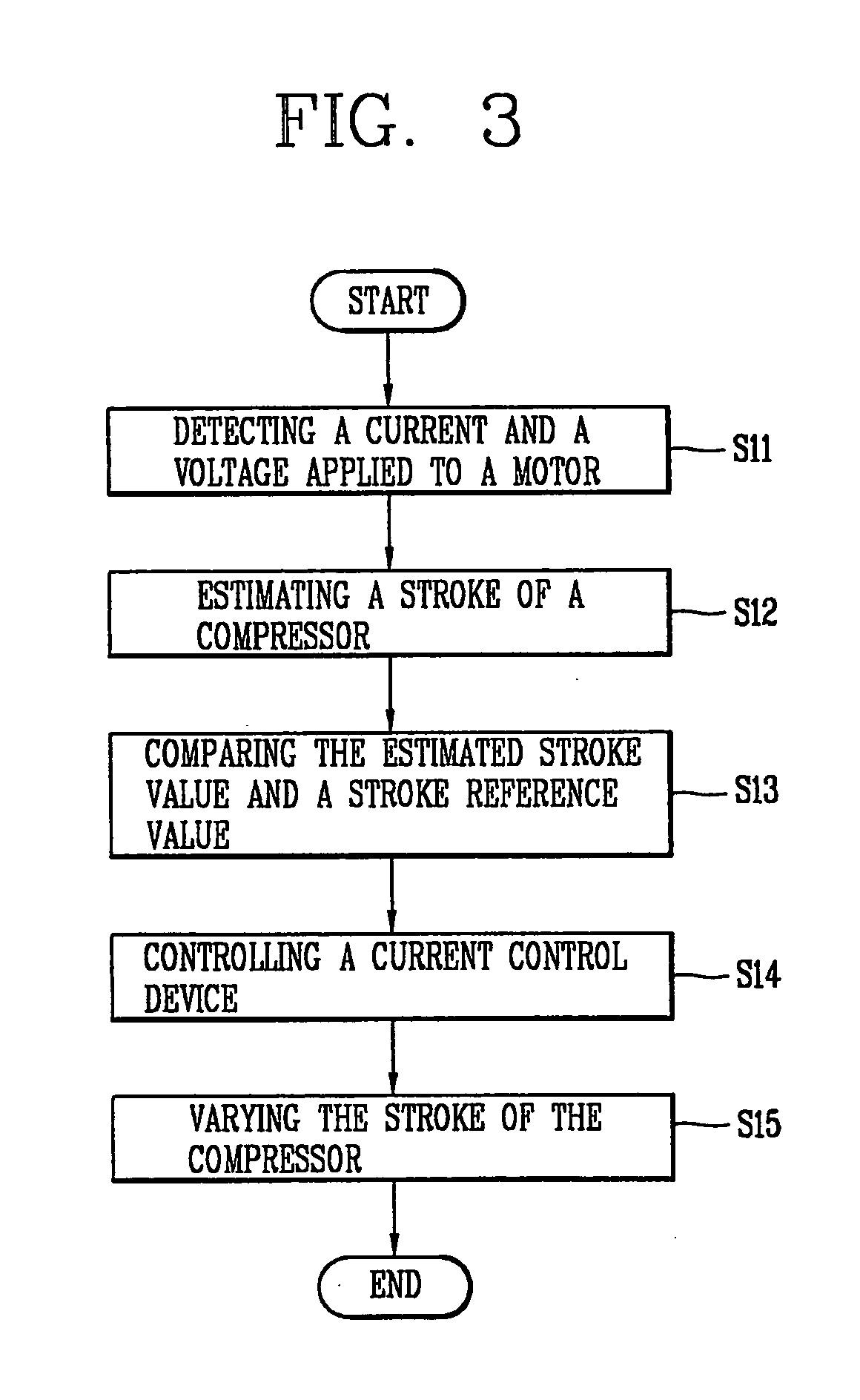
In an operation control apparatus and a method thereof, the compressor can be protected from overloading through a current control device instead of an OLP (Over Load Protector) and a PTC thermistor (Positive Temperature Coefficient thermistor). The operation control apparatus includes: a stroke estimated unit for estimating a stroke of the compressor on the basis of a current and a voltage applied to an interior motor of the compressor and a motor constant of the interior motor; a control unit for generating a control signal for varying a stroke of the compressor on the basis of the estimated stroke value and a preset stroke reference value; and a current control means being turned on / off so as to vary a stroke voltage applied to the interior motor of the compressor.

Description

TECHNICAL FIELD [0001] The present invention relates to a compressor and, particularly to an operation control apparatus for a compressor used for a refrigerator and a method thereof. BACKGROUND ART [0002] Generally, in a compressor, particularly a reciprocating compressor, compression efficiency is higher than a general compressor since there is no crankshaft for converting a rotational movement into a linear movement and thus a friction loss is small. [0003] In case that the reciprocating compressor is used for a refrigerator or an air conditioner, as varying a stroke voltage applied to the reciprocating compressor (interior motor of the compressor), being able to vary a compression ratio, so that freezing capacity can be controlled. The operation controlling apparatus for the reciprocating compressor will now be described with reference to FIG. 1. [0004]FIG. 1 is a block diagram showing a configuration of the operation control apparatus for the reciprocating compressor according ...

Claims


Application Information

Patent Timeline
IPC IPC(8): F25B49/00F25B1/00F04B35/04F25D29/00
CPCF04B35/045F04B2203/0402F04B2203/0401F25D29/00
Inventor JUN, YOUNG-HOANSHIN, DONG-HEEBAE, GYOO-JONGLEE, WOO-GEUN
Owner LG ELECTRONICS INC
Learn More