Method and apparatus for detecting analyte with filter

Inactive Publication Date: 2006-03-02
NAT UNIV OF SINGAPORE
View PDF13 Cites 25 Cited by
  • Summary
  • Abstract
  • Description
  • Claims
  • Application Information

AI Technical Summary

Benefits of technology

[0010] Advantageously, it is not necessary to pre-concentrate the sample as the analyte can concentrate at the filter when the sample is passed through the filter. Since no or little analyte in the sample will be lost and the analyte can accumulate at the filter, the analyte concentration in the sample does not need to be high. The detection can be performed in less time than many conventional techniques. Further, since more than one signal producing members may attach to the analyte, signal strength and hence detection sensitivity can be high. It is also less expensive to prepare a carrying fluid that has a low concentration of signal producing members, which is sufficient as the carrying fluid can be flown by the trapped analyte for any desired period of time. Re-use of the carrying fluid is also possible. Moreover, with a single filter more than one type of analytes may be detected either separately or simultaneously.
[0012] In another aspect of the invention there is provided a device for detecting an analyte, comprising a body having walls defining a fluid path; a filter for trapping the analyte in the fluid path but allowing passage of signal producing members smaller in size than the analyte and having affinity to specifically attach to the analyte; the analyte trapped in the path by the filter; and at least one of the walls allowing transmission of a signal produced by the signal producing members attached to the analyte such that the analyte can be detected by sensing the signal.
[0014] In another aspect of the invention, there is provided a device for detecting an analyte, comprising: a body having walls defining a fluid path; a filter for trapping the analyte in the fluid path but allowing passage of signal producing members smaller in size than the analyte and having affinity to specifically attach to the analyte; a screen disposed upstream of the filter in the fluid path for blocking objects larger than the analyte; and at least one of the walls allowing transmission of a signal produced by the signal producing members attached to the analyte such that the analyte can be detected by sensing the signal.

Problems solved by technology

If the analyte is trapped at the filter, some signal producing members can attach to the analyte and be trapped as well.

Method used


Image

  • Method and apparatus for detecting analyte with filter
  • Method and apparatus for detecting analyte with filter
  • Method and apparatus for detecting analyte with filter

Examples


example

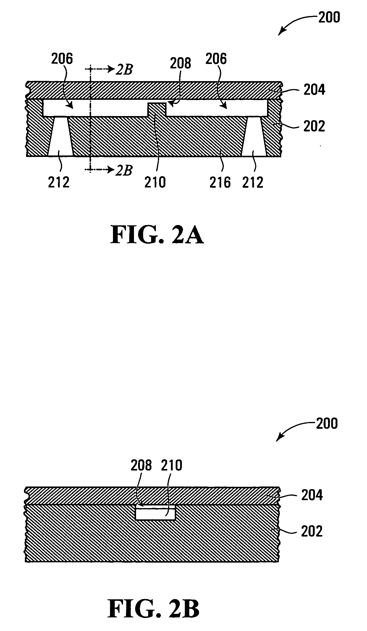
[0077]FIG. 6A is an image taken during an example procedure for detecting florescent beads. The device used had three parallel weir-type filters as illustrated in FIGS. 2A and 2B. The weir gaps were about 3-4 μm deep. The beads had diameters of 1, 4, 10 and 15 μm. The beads were injected into the conduits and flushed with water at a flow rate of 20 μl / min. An epifluorescence microscope was used to monitor the locations of the beads. The microscope had a cooled charge-coupled device (CCD) camera, a 100W HBO™ bulb, and appropriate filter sets. As shown, the larger beads were all trapped before the weirs. It was observed that the 1 μm beads passed through the weirs. A similar test with a device of weirs about 1 to 2 μm deep showed similar result: only 1 μm beads passed through the filer and the larger beads were trapped.

[0078]FIGS. 6B and 6C are images taken in procedures carried out for detecting microbial cells Cryptosporidium spp. and Giardia spp., both being protozoan cells, using...


PUM


Abstract

To detect an analyte, a fluid is flown through a filter. The fluid carries signal producing members smaller in size than the analyte and having affinity to specifically attach to the analyte. The filter is adapted for trapping the analyte while allowing passage of unattached ones of the signal producing members. A signal produced by one or more of the signal producing members can be sensed upstream of the filter to detect the analyte trapped by the filter.

Description

CROSS-REFERENCE TO RELATED APPLICATION [0001] This application claims priority from U.S. provisional application No. 60 / 511,114, entitled “Integrated Filter-based MEMS Device for Parallel Concentrating and Detection of Microbial Cells” and filed Oct. 15, 2003, which is incorporated herein by reference.FIELD OF THE INVENTION [0002] The present invention relates generally to sample analysis, and more particularly to method and apparatus for detection of analytes. BACKGROUND OF THE INVENTION [0003] Rapid and accurate detection of microbial cells in fluids can save life. For example, it is estimated that infectious diseases cause nearly 20 million deaths a year, a majority of which are transmitted through physical contact with contaminated water. Early detection of infectious micro-organisms in water sources can thus significantly reduce risks of outbreaks of certain infectious diseases, or biological terror attacks. Detection of microbial cells in fluids also has various other applicat...

Claims


Application Information

Patent Timeline
IPC IPC(8): G01N31/22G01N33/53G01N33/537
CPCB82Y5/00G01N33/56905G01N33/537B82Y10/00
Inventor LIU, WEN-TSOANG, SIMON S.ZHU, LINNG
Owner NAT UNIV OF SINGAPORE
Why Eureka
Try Eureka