
Imaging apparatus

Inactive Publication Date: 2006-03-02
NIKON CORP
View PDF5 Cites 11 Cited by
  • Summary
  • Abstract
  • Description
  • Claims
  • Application Information

AI Technical Summary

Benefits of technology

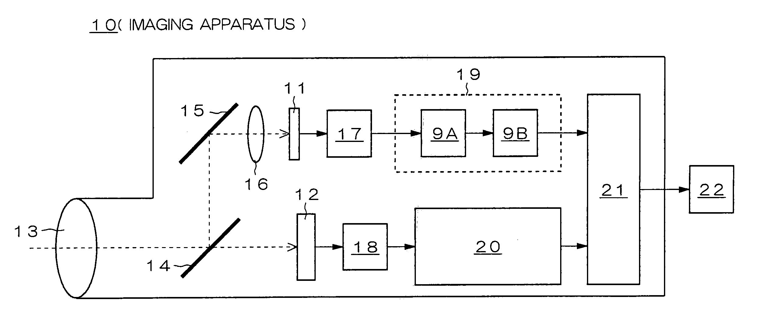
[0007] It is an object of the present invention to provide an imaging apparatus which can increase recording resolution while reducing the amount of data to be handled during compression processing.

Problems solved by technology

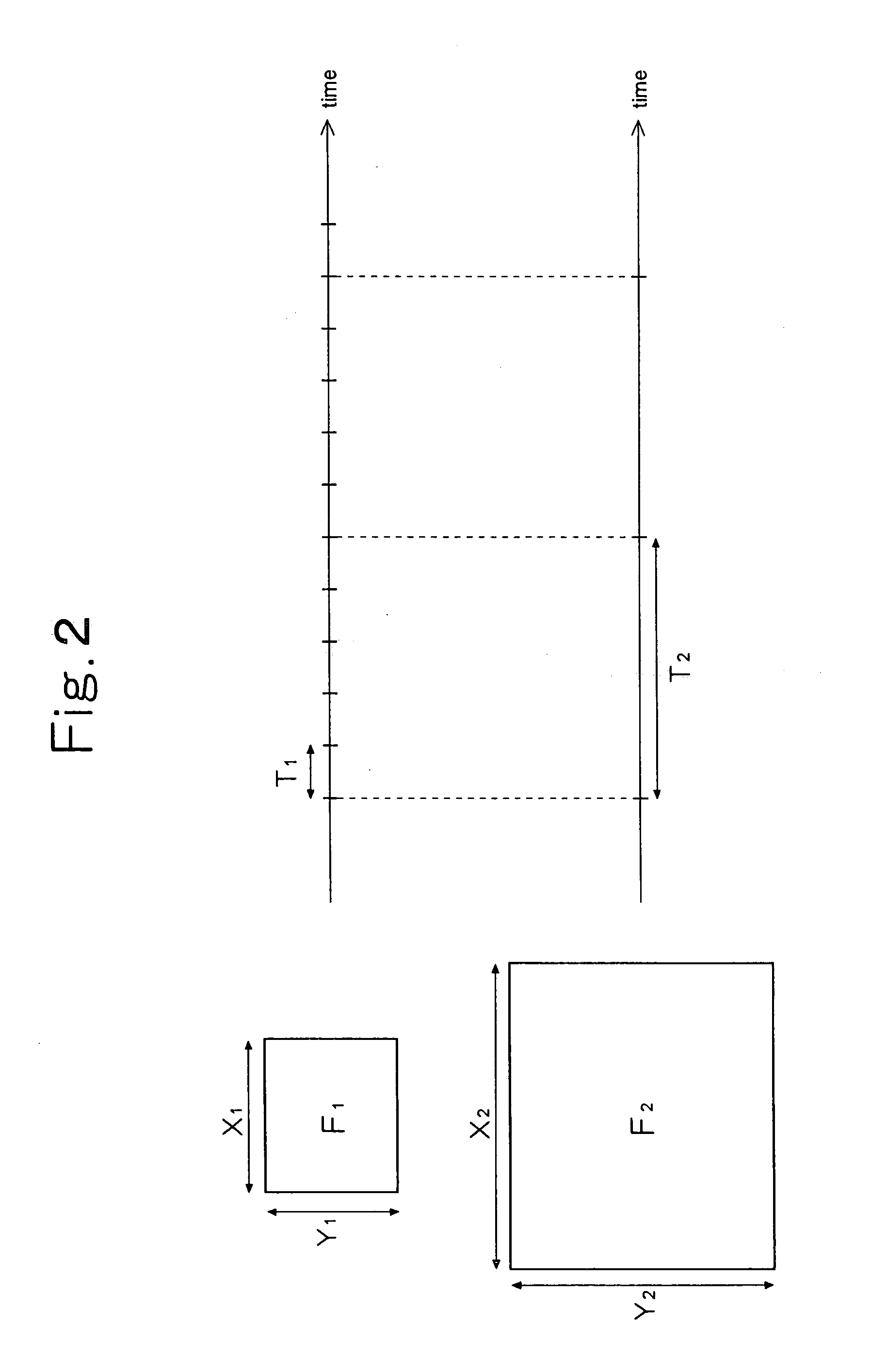
Therefore, when recording resolution is increased in order to obtain the moving image of high definition, the resolution of each frame increases, the amount of data to be handled during the compression processing increases, and processing speed lowers, which result in a slow imaging frame rate.

Method used


Image

  • Imaging apparatus
  • Imaging apparatus
  • Imaging apparatus

Examples


modification example

[0051] Incidentally, according to the above-described embodiment, the example of detecting the motion vectors M1, M2, . . . , MN in the inter-frame compression by the data processing part 19 is explained. However, the present invention is not limited to the above. The present invention may be applied to the case where a predictive frame after the motion compensation using the vector distribution information in the low resolution (FIG. 5) is generated and a difference frame between the predictive frame and the frame F1 in the low resolution which is outputted from the imaging device 11 is generated, as necessary.

[0052] In this case, in the resolution conversion part 9B, the conversion processing of the above-described difference frame in the low resolution into a difference frame in the high resolution is also performed, in addition to the resolution conversion processing of the vector distribution information (FIG. 5→FIG. 6). This conversion processing can also be performed similar...


PUM


Abstract

An imaging apparatus is disclosed which can increase recording resolution while reducing data amount handled during compression processing. The imaging apparatus includes a first imaging unit capturing an image of a subject and outputting a frame in first resolution in first time intervals, a second imaging unit capturing the image of the subject and outputting a frame in second resolution higher than the first resolution in second time intervals longer than the first time intervals, a detecting unit detecting motion vectors between the adjacent frames outputted from the first imaging unit and outputting the motion vectors as vector distribution information in the first resolution, a converting unit converting the vector distribution the in the first resolution into vector distribution information in the second resolution, and a recording unit recording on a storage media the vector distribution information in the second resolution and the frames outputted from the second imaging unit.

Description

CROSS-REFERENCE TO RELATED APPLICATIONS [0001] This application is based upon and claims the benefit of priority from Japanese Patent Application No. 2004-252451, filed on Aug. 31, 2004, the entire contents of which are incorporated herein by reference. BACKGROUND OF THE INVENTION [0002] 1. Field of the Invention [0003] The present invention relates to an imaging apparatus that shoots the moving image of a subject. [0004] 2. Description of the Related Art [0005] The imaging apparatus which shoots the moving image compresses a plurality of frames which are sequentially outputted from an imaging device in various ways, in order to reduce the amount of data when recording. An internal circuit which performs compression processing takes in the frames in the same resolution in constant time intervals, and sequentially performs intra-frame compression processing and inter-frame compression processing (refer to Japanese Unexamined Patent Application Publication No. Hei 9-23405, for example...

Claims


Application Information

Patent Timeline
IPC IPC(8): H04N5/228H04N5/225H04N5/232
CPCH04N5/2258H04N5/23232H04N19/513H04N19/59H04N19/436H04N19/53H04N19/587H04N19/61H04N23/45H04N23/951
Inventor NISHIZAWA, TSUTOMU
Owner NIKON CORP
Learn More