
Vehicle wheel and overlay assembly

a technology for overlaying and vehicles, applied in the field of vehicles, can solve the problems of significant cost increase, insufficient cover of the rim flange lip of the wheel,

Inactive Publication Date: 2006-03-02
LACKS INDUSTRIES INC
View PDF25 Cites 18 Cited by
  • Summary
  • Abstract
  • Description
  • Claims
  • Application Information

AI Technical Summary

Benefits of technology

[0035] It is yet another object and advantage of the present invention to take advantage of the circumferential indentation or groove on the outboard surface of the flange lip of the rim flange of the wheel to create such reduced surface contact between the overlay and the wheel.
[0036] The other objects and advantages of the present invention are that since, the overlay does not wrap around the flange lip of the rim flange of the wheel, the overlay will protect the flange lip of the wheel from chipping due to objects hitting the flange lip of the wheel. The overlay is not vulnerable to damages occurring from “run flat” conditions, servicing of the tires, and removing and attaching of wheel balance weights. There are no sharp edges anywhere near the tire, which could damage the rubber of the tire. Also, the overlay will not make the wheel and overlay assembly look larger than its actual size.
[0037] Finally, it is an object of the present invention to combine all previously mentioned objects and advantages to offer a consumer a wheel and overlay assembly, which creates an aesthetically pleasing impression of a cladding / wheel assembly made of a single chrome plated wheel, whereby the entire visible outboard surface of the overlay appears to be the entire outboard surface of the wheel, and not a separately attached component of the assembly.
[0038] Other objects and advantages of the present invention will be more apparent after a reading of the following detailed description is taken in conjunction with the drawings provided.BRIEF DESCRIPTION OF THE SEVERAL VIEWS OF DRAWINGS
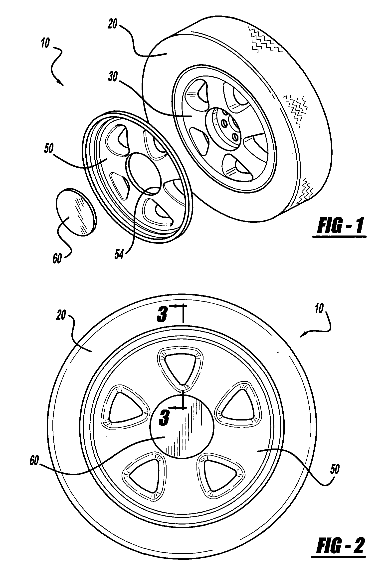
[0039]FIG. 1 illustrates an exploded perspective view of a vehicle wheel assembly including an overlay and a tire mounted to a wheel;
[0040]FIG. 2 illustrates a side view of the vehicle wheel assembly of the present invention;

Problems solved by technology

As with the Chase prior art, the wheel cover covers most of the wheel's outboard surface of the wheel but it does not adequately cover the flange lip of the rim flange of the wheel.
Again, as in Beam, this wheel cover radially extends outward, but fails to adequately cover the flange lip of the rim flange of the wheel.
Each of these prior art configurations can result in a significant cost increase if the adhesive, due to improper manufacturing control, squeezes out from underneath the cover to collect at the interface of the cover and wheel rim flange.
Unfortunately, there are several drawbacks in using a molded in-situ urethane cover for a wheel.
Since the urethane material is directly molded onto the outboard surface of the wheel, the urethane material on the outboard surface of the wheel will have a tendency to break down in certain areas of the wheel under extremely high temperatures.
Such high temperatures in the disk of a wheel can otherwise distort or melt the plastic wheel cover.
This requirement is somewhat complicated, expensive, and may be impractical for just in time manufacturing program.
This thin layer of urethane molding along the outboard flange edge of the wheel is highly susceptible to chipping, and may result in an aesthetically unacceptable surface appearance.
Additionally, the stainless steel overlays of Beam and Murray et al. can cause galvanic action along the interface where the overlay engages into the groove of rim flange of the hot roll steel wheel resulting in deposits of corrosion, commonly known as “red rust.” Further, the exposed flange lip of the rim flange of the wheel circumscribing the periphery of the overlay manifests that this is a cladded wheel and tends to make the wheel look smaller than its actual size.
Wheel and wheel cover tolerances may stack up to reveal a noticeable eccentricity between the wheel cover and the wheel.
For instance, where the wheel cover may adequately cover one arcuate sector of the wheel's outboard surface at the radial outer periphery of the wheel, an opposite arcuate sector of the outboard surface may be insufficiently covered.
This situation will tend to reveal an obvious non-symmetrical and aesthetically unacceptable appearance (not chrome-plated) of the wheel and overlay assembly.
Additionally, the exposed flange lip of the rim flange of the wheel along the radial outer periphery of the rim flange of the overlay also will tend to make the wheel look smaller and less robust to the consumer.
Although, Todd discloses that a peripheral edge of the fascia extends to an edge of the wheel, it fails to clearly disclose whether it actually covers the flange lip of the rim flange of the wheel.
As in Todd, Hodge et al. does not clearly disclose whether the wheel cover overlaps the flange lip of the rim flange of the wheel.
However, this invention, like the previous prior art, has several problems.
For example, these type of wheel cover assemblies are not without their problems, the assembly of the stainless steel wheel cover in Heck et al. requires an over bend to accommodate the natural spring-back of the radial end.
Although, the references of the second group of prior art address some of the problems associated with the references of the first group of prior art, they nonetheless fail to identify and address several additional problems, which still exist.
Tire servicing, radial load deflections during operation, and “run flat” conditions are all situations in which permanent damage to the overlay or tire can occur.
During the installation and removal of the tire, service equipment that locates on the extreme periphery of the rim flange of the wheel will damage a wheel cover that wraps around the flange lip of the rim flange of the wheel.
Likewise, where the outermost diameter of the wheel cover is greater than that of the wheel, it is likely that many wheel covers from the prior art references would be damaged upon either installation or removal of wheel balance weights.
Additionally, such wheel covers are more likely to be cracked and / or chipped when a wheel hits a curb or a pothole.
Similar damages may occur as a result of material handling in the production process when outer diameter of assembled wheels collide into one another such as it happens on a gravity feed conveyor.
In addition, when a wheel and overlay assembly rolls on a surface without a tire, the surface treatment (chrome plating) of the wheel cover will chip since the cover wraps around the outside diameter of the wheel.
This appearance of the wheel and overlay assembly adversely affects the overall aesthetic of the vehicle.
Such solution is not tolerable since it affects the structural integrity of the wheel as well as significantly increases the cost of producing the wheel only.
The chromium plated surface layer of such deflected and distorted wheel cover will be subject to excessive stresses, which could lead to spider cracks in the chrome plated layer.
Since the tire sits very close to such grooves, such unseated edge of an overlay may cut into the tire, causing a safety related problem.
The sharp peripheral edge of an overlay, which wraps around the rim flange of a wheel, may tear into the rubber tire causing expensive damage.
If the robotic application of the adhesive at assembly cannot be carefully controlled, the adhesive will likely flow beyond the outer edges of the wheel and overlay assembly and require costly clean-up operations.
Eventually, tolerance variations in the application of the adhesive may result in squeeze out along the outer periphery of the wheel and overlay assembly necessitating a costly clean up procedure.
This squeeze out of adhesive, if not properly cleaned up, is aesthetically unacceptable to the car assembly client.
Since the aesthetic objective is to provide a wheel / cladding assembly that is perceived to be an actual chrome plated wheel, any amount of squeeze out of adhesive along the mating surfaces of the cover and wheel is unacceptable.
In addition, none of the references has addressed the issue of friction between the outer peripheral edge of the wheel cover and the flange lip of the rim flange of the wheel.
If no attempts are made to control this friction between the wheel cover and the wheel, during normal operation of a vehicle, excessive squeak or noise will emit from the wheel and overlay assembly creating an audible sound pollution around the vehicle.

Method used


Image

  • Vehicle wheel and overlay assembly
  • Vehicle wheel and overlay assembly
  • Vehicle wheel and overlay assembly

Examples


Embodiment Construction

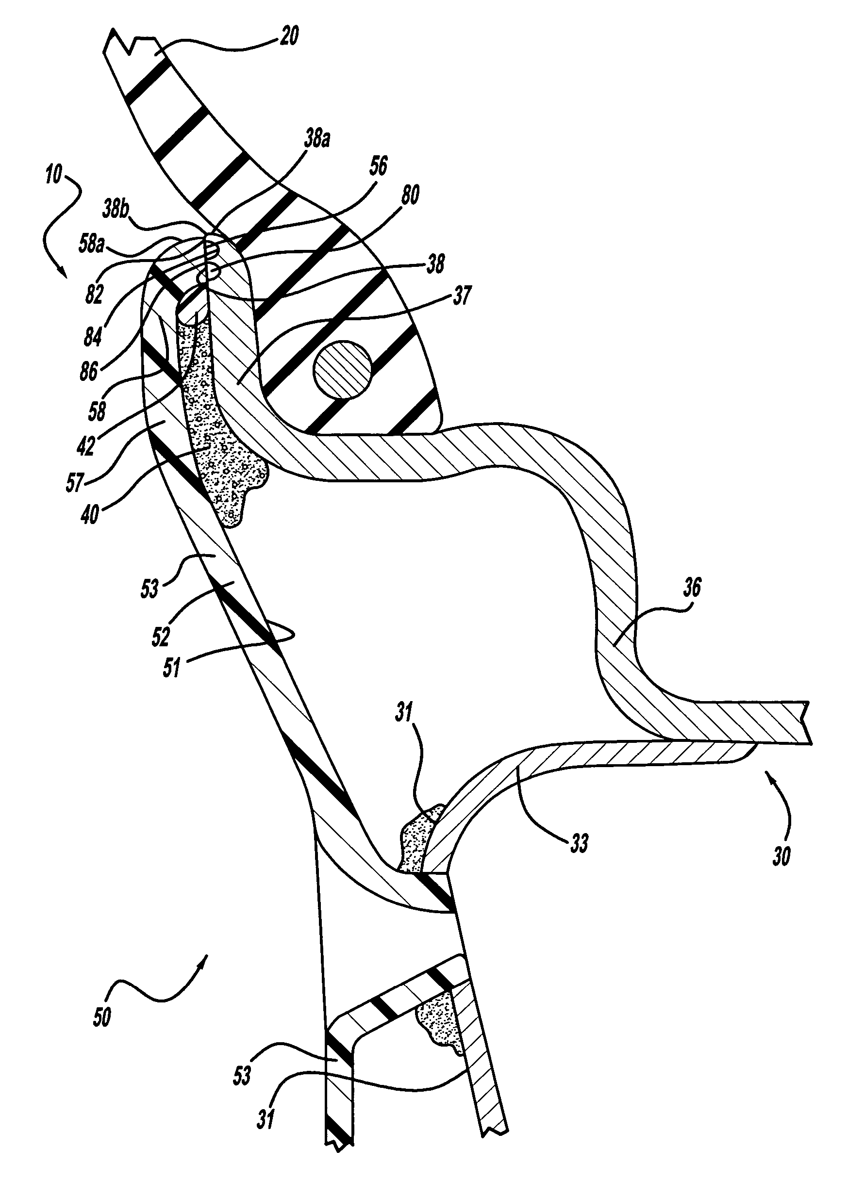
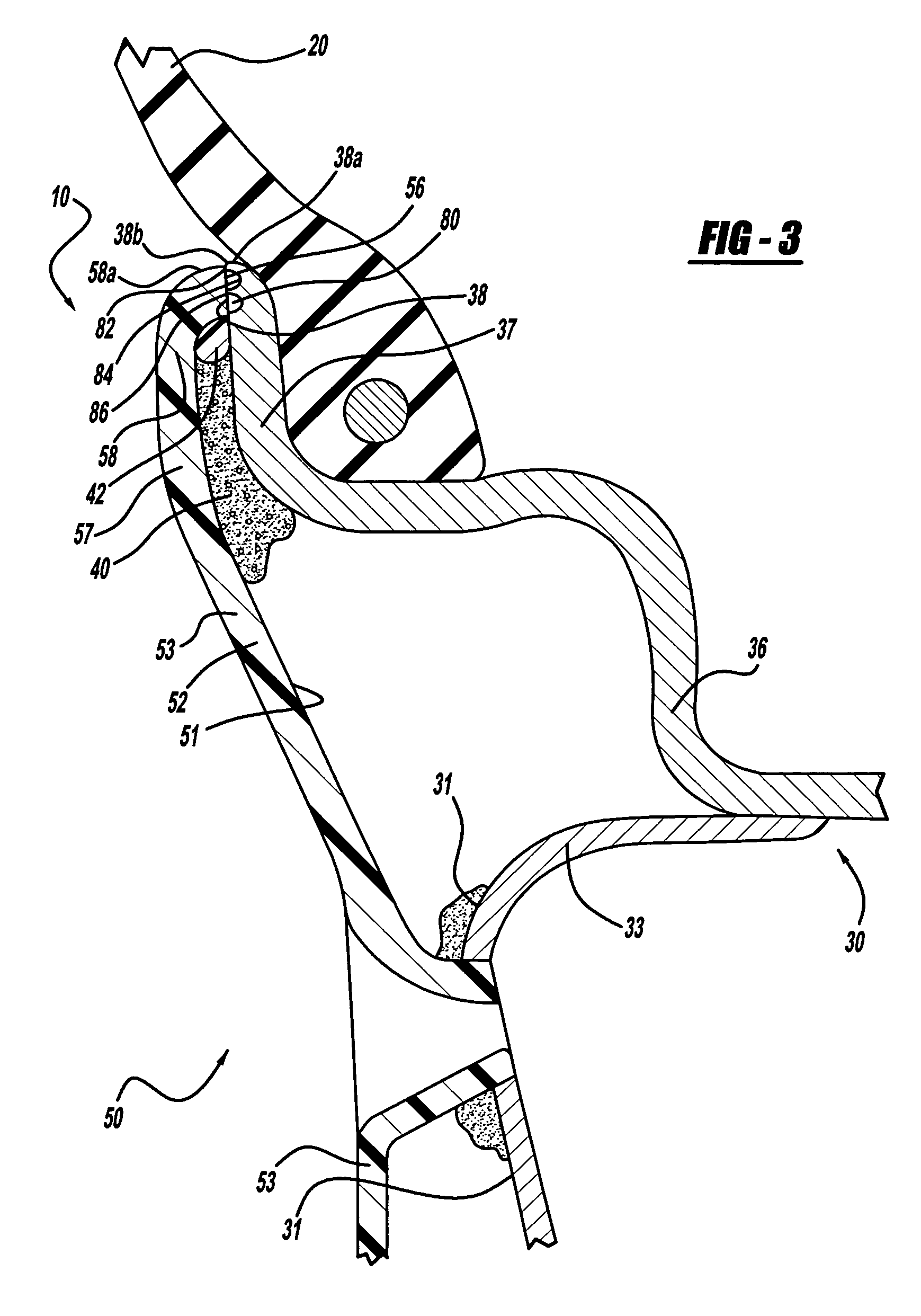
[0051] Referring now to the drawings and with particular attention to FIGS. 1-3, there is illustrated in FIG. 1 an exploded perspective view of a vehicle cladded wheel assembly, indicated generally at 10, wherein the wheel is constructed according to any one of the following well known wheel constructions: 1) a “bead seat attached wheel,” such as shown in FIG. 4 of U.S. Pat. No. 5,188,429 to Heck et al.; 2) a “well attached wheel,” such as shown in FIG. 3 of U.S. Pat. No. 5,188,429 to Heck et al.; 3) a one-piece cast or forged alloy wheel, such as shown in U.S. Pat. No. 5,636,906 to Chase; 4) a two-piece welded steel wheel, offset (drop center rim) as shown in FIG. 2 of U.S. Pat. No. 5,597,213 to Chase; 5) a partial rim and a full face, such as shown in FIG. 2 of U.S. Pat. No. 5,595,423 to Heck et al.; or 6) a “Euro” flange construction such as shown in U.S. Pat. No. 4,438,979 to Renz et al. Because of these various prior art wheel constructions, the Society of Automotive Engineers ...


PUM


Abstract

A vehicle wheel and overlay assembly. The assembly includes a wheel having a rim flange that terminates in a flange lip having an outboard surface and a radially outermost edge. At least one circumferential indentation or groove is formed on the outboard surface of the flange lip to intercept and contain excess adhesive that may radially flow toward the outer edges of the assembly necessitating a costly clean up. An overlay is attached to the wheel outboard surface. The overlay radially extends outward and terminates in a rim flange. This rim flange includes a radially outermost lip, which is aligned with the outermost edge of the wheel flange lip within a predetermined circumferential margin such that, the rim flange of the overlay covers at least a portion of the wheel flange lip without wrapping around the periphery of the wheel. This configuration gives a visible impression that this is a one-piece wheel, and the overlay is not a separately attached component. The circumferential indentation or groove creates cavity on the outboard surface of the flange lip and appreciably reduce surface contact between the overlay and the wheel, resulting in reduced friction between the surfaces. The reduced friction helps minimize the squeaking or noise from the overlay rubbing against the wheel.

Description

CROSS REFERENCE TO RELATED APPLICATION [0001] Not applicable. FEDERALLY SPONSORED RESEARCH OR DEVELOPMENT [0002] Not applicable. REFERENCE TO A MICROFICHE APPENDIX [0003] Not applicable. BACKGROUND OF THE INVENTION [0004] 1. Field of the Invention [0005] The present invention generally relates to vehicle wheels that are equipped with an attached chromium-plated wheel cover, cladding or overlay. The metal plated overlay's bond strength permits the overlay to be shaped and contoured on to the shape of the wheel, so as to maximize aesthetic effects. [0006] 2. Description of the Related Art [0007] Decorative wheel trim in the form of chromium plated wheel covers or claddings adhesively attached to steel or aluminum wheels have been emphasized for providing enhancing aesthetic features of automotive wheels. In addition, to improving the appearance of unadorned standard steel wheels, significant styling flexibility is available to the stylist to create unique aesthetic characteristics for...

Claims


Application Information

Patent Timeline
IPC IPC(8): B60B7/00
CPCB60B7/0013B60B7/18B60B7/06
Inventor HOUTEN, GARRY VAN
Owner LACKS INDUSTRIES INC
Learn More