Arc-hydrolysis fuel generator with supplemental energy recovery

a fuel generator and arc-hydrolysis technology, applied in the field of fuel generators, can solve the problems of large water consumption of previous devices and methods, substantial energy waste, and substantial energy loss in the process of producing fuel, and achieve the effect of harvesting waste energy

Inactive Publication Date: 2006-03-02
VILLALOBOS VICTOR M
View PDF33 Cites 11 Cited by
  • Summary
  • Abstract
  • Description
  • Claims
  • Application Information

AI Technical Summary

Benefits of technology

[0033] Another feature and advantage of the present invention is its ability to produce carbon monoxide and hydrogen gas in combination.
[0034] Still another feature and advantage of the present invention is its ability to harvest the waste energy created during arc-hydrolysis through utilization of a magnetic field.
[0035] Yet another feature and advantage of the present invention is its ability to desalinize water, while concurrently generating fuel.
[0036] Yet still another feature and advantage of the present invention is ability to recycle animal and / or vegetable waste, while concurrently generating fuel.
[0037] A further feature and advantage of the present invention is its ability to selectively generate heat, while concurrently generating fuel.
[0038] Still a further feature and advantage of the present invention is its ability to provide cyclical energy motion for pumping.

Problems solved by technology

While energy utilized in production of hydrogen and / or carbon monoxide / dioxide can be recovered through combustion, there is a substantial amount of energy lost in the process of producing the fuel.
However, there remains a substantial quantity of energy waste in the electric arc discharge.
Additionally, previous devices and methods disadvantageously consume great quantities of water; in particular, 1500 gallons per hour water is needed for a 50 KWh unit.

Method used


Image

  • Arc-hydrolysis fuel generator with supplemental energy recovery
  • Arc-hydrolysis fuel generator with supplemental energy recovery
  • Arc-hydrolysis fuel generator with supplemental energy recovery

Examples


Embodiment Construction

[0211] In describing the preferred and selected alternate embodiments of the present invention, as illustrated in FIGS. 1-10, specific terminology is employed for the sake of clarity. The invention, however, is not intended to be limited to the specific terminology so selected, and it is to be understood that each specific element includes all technical equivalents that operate in a similar manner to accomplish similar functions.

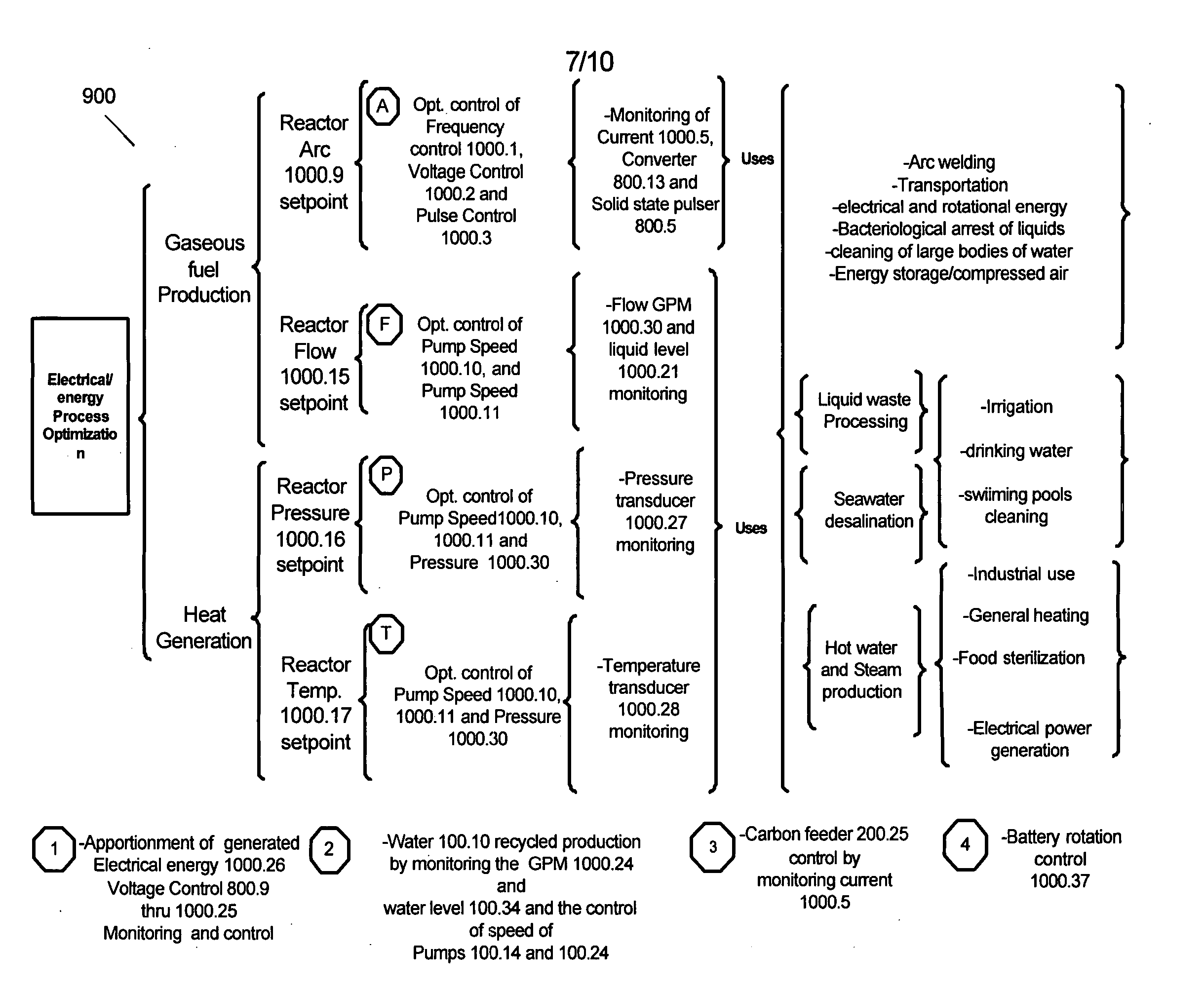
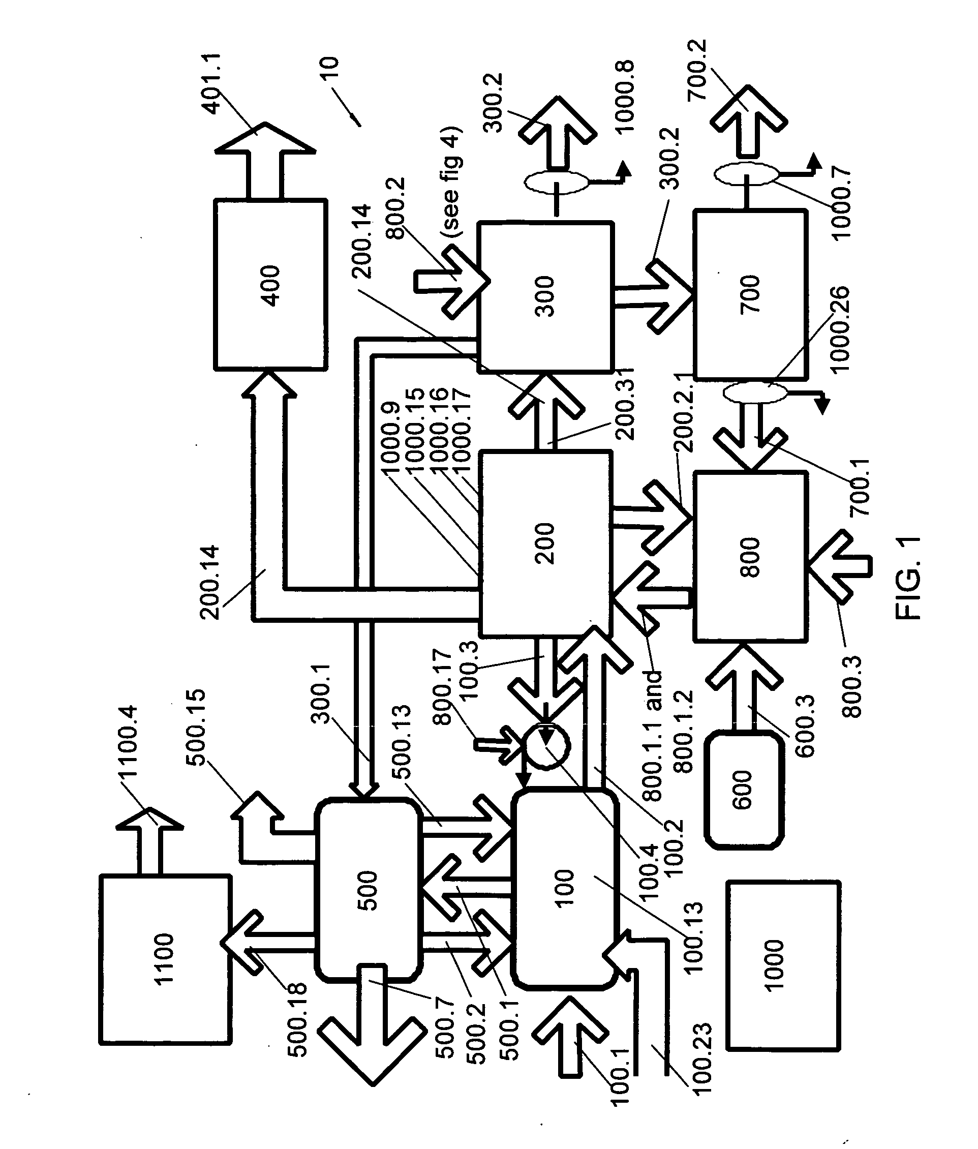
[0212] Referring now to FIGS. 1-2, 3B-8A and 9-10, the present invention in the preferred embodiment is arc-hydrolysis gaseous fuel generator 10 with supplemental energy recovery, preferably via formation of an arc discharge via anodes 200.4.1 and 200.5.1, wherein, preferably, anodes 200.4.1 and 200.5.1 have metal collector 200.2 disposed therearound as a means for induction, wherein metal collector 200.2 comprises, for exemplary purposes only, a grid or a coil. Energy from arc discharge electrolyzes water or biomass contained within arc-hydrolysis unit 200...


PUM

PropertyMeasurementUnit
temperatureaaaaaaaaaa
voltageaaaaaaaaaa
temperatureaaaaaaaaaa

Abstract

An arc-hydrolysis fuel generator and method of use thereof, the generator comprising an inductor placed around an arc-hydrolysis unit, wherein the inductor recovers. magnetic energy generated by the electric arc discharge to supplement the energy recoverable from the hydrogen and/or carbon monoxide/dioxide fuel generated from water and/or biomass by the arc-hydrolysis unit. The arc-hydrolysis fuel generator may further comprise a water vapor recovery system, a steam generation system and/or a gas liquefying system, utilizing fuel generated by the arc-hydrolysis fuel generator during use.

Description

PRIORITY CLAIM [0001] To the fullest extent permitted by law, the present non-provisional patent application claims priority to, and the full benefit of the following co-pending applications: (1) provisional patent application entitled “Water Fueled Pneumatic Energy Storage and Generator Apparatus”, filed on Aug. 30, 2004, having assigned Ser. No. 60 / 605,706; (2) provisional patent application entitled “Self-sustaining Arc-hydrolysis Gaseous Fuel Generator”, filed on Sep. 7, 2004, having assigned Ser. No. 60 / 607,770; (3) provisional patent application entitled “Self-sustaining Arc-hydrolysis Gaseous Fuel Generator”, filed on Sep. 15, 2004, having assigned Ser. No. 60 / 610,072; and provisional patent application entitled “Multiple Use Self-sustaining Arc-hydrolysis Gaseous Fuel Generator”, filed on Oct. 5, 2004, having assigned Ser. No. 60 / 615,975. TECHNICAL FIELD [0002] The present invention relates generally to fuel generators, and more specifically to a gaseous fuel generator and p...

Claims


Application Information

Patent Timeline
Patent Type & Authority Applications(United States)
IPC IPC(8): C25C1/02
CPCB01J19/02Y02E60/364B01J2219/0209B01J2219/0809B01J2219/0839B01J2219/0869B01J2219/0871B01J2219/0875B01J2219/0877B01J2219/0879C01B3/042C01B3/342C01B2203/0233C01B2203/0861C01B2203/84B01J19/088Y02E60/36
Inventor VILLALOBOS, VICTOR M.
Owner VILLALOBOS VICTOR M
Why Eureka
Try Eureka