
Alkaline impregnated filter element, and methods

a filter element and impregnated technology, applied in gravity filters, filtration separation, separation processes, etc., can solve the problems of reducing the useful life tortuous path for air flowing, and reducing the useful life of filters. , to achieve the effect of enhancing the oxidation reaction, reducing the life of prior art filters, and reducing the number of oxidative reactions

Inactive Publication Date: 2006-03-02
DONALDSON CO INC
View PDF8 Cites 96 Cited by
  • Summary
  • Abstract
  • Description
  • Claims
  • Application Information

AI Technical Summary

Benefits of technology

The present invention is a contaminant-removing filter that has a basic material and a promoter to increase its life. Prior to this invention, filters with basic materials did not have a long life because of moisture. The promoter enhances the oxidation reaction between the basic material and the acid gas, which removes the contaminant. The filter has a substrate, such as fibrous or porous material, with passages for gas flow. The substrate can be made of fibrous or polymeric material, or a combination of both. The filter can be used in high purity applications, such as semiconductor processing, to remove acidic contaminants from air or other gas streams. The ratio of promoter to basic material can be 1:1 to 1:5000. The method of making the filter involves applying a mixture of basic material and promoter to the substrate.

Problems solved by technology

Silicon containing materials, such as silanes, siloxanes, silanols, and silazanes can be particularly detrimental contaminants for some applications.
Additionally, many toxic industrial chemicals and chemical warfare agents must be removed from breathing air.
These tightly packed beds result in a torturous path for air flowing through the bed.
However, as a result of the tightly packed beds, a significant pressure loss is incurred.
Unfortunately, these methods do not adequately address the pressure loss issue, however, and can create an additional problem of non-uniform flow velocities exiting the bed.
U.S. Pat. No. 6,071,479 (Marra et al.) has attempted to provide a suitable article for removal of contaminants from a gas stream, however, various disadvantages and undesirable features are inherent in the article of Marra et al.
For example, the media is not designed for long-term and / or high purity filtration applications.
In accordance with the invention of Marra et al., paper media impregnated with base, and a humectant and / or urea is supposedly a suitable contaminant removal article; however, when in actual use, such a product does not provide acceptable performance.
Such adhesive materials are known to off-gas contaminants, some of which react with or bind with the contaminant-removal material, thus decreasing the amount available for removing contaminants from the gas flowing therethrough.

Method used


Image

  • Alkaline impregnated filter element, and methods
  • Alkaline impregnated filter element, and methods
  • Alkaline impregnated filter element, and methods

Examples


examples

[0081] The following non-limiting examples will further illustrate the invention. All parts, percentages, ratios, etc., in the examples are by weight unless otherwise indicated.

[0082] The following substrate body was used for the example contaminant-removal elements:

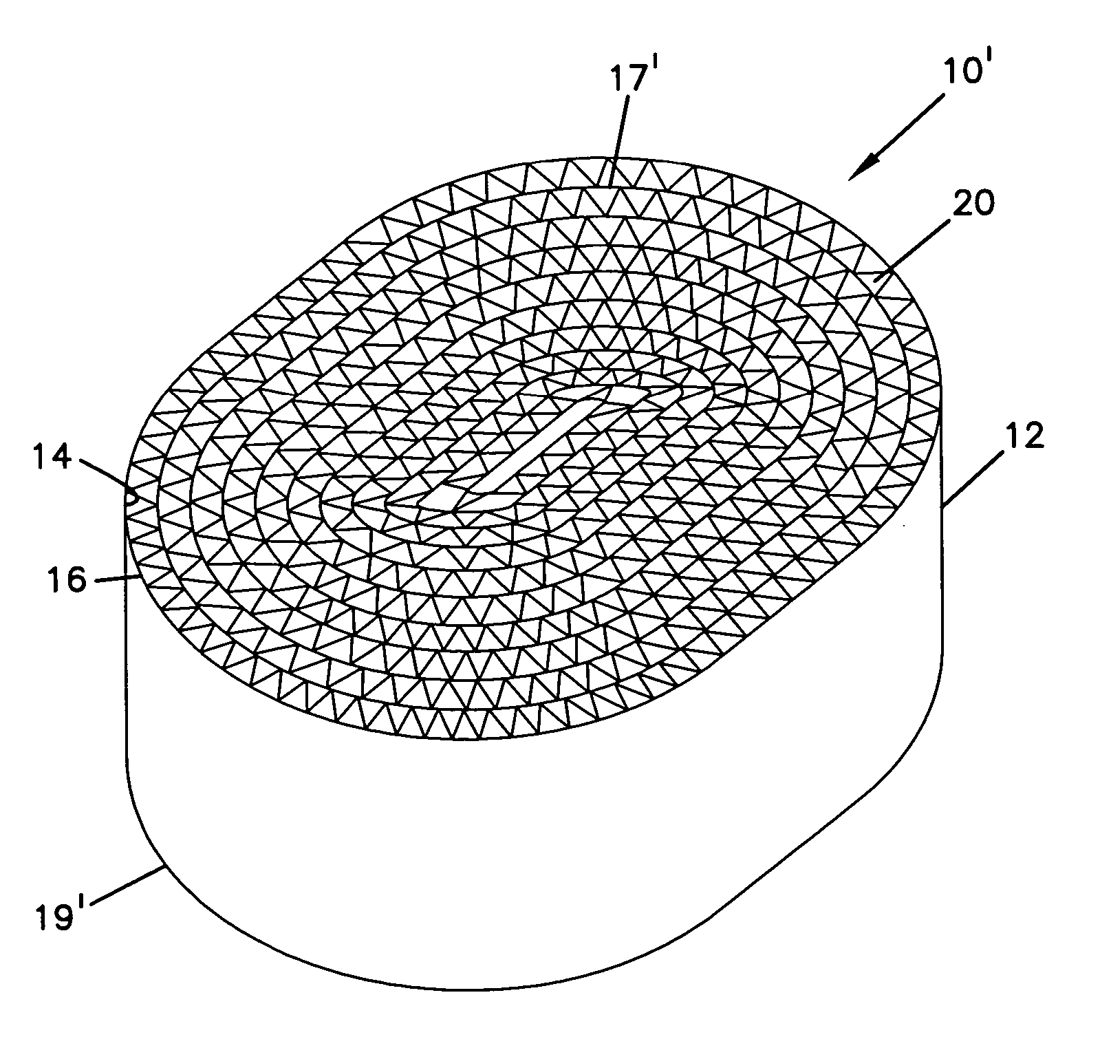
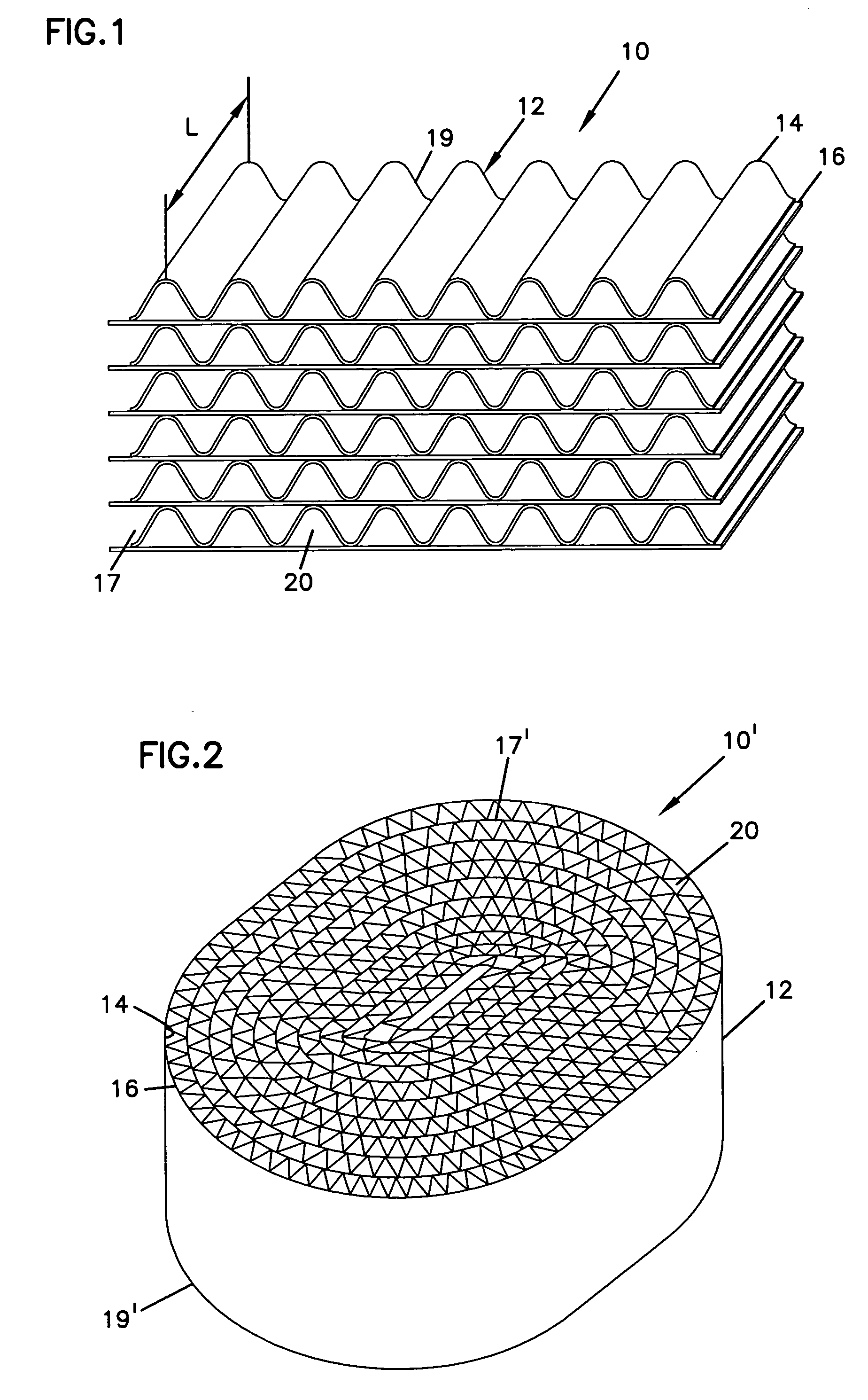
[0083] Body 1: Body 1 was similar to that of FIG. 2, formed by alternating a flat facing sheet and a sinusoidal corrugated sheet. The sheets were made from 60% cellulose fibers and 40% PET fibers. The sheets were wrapped to form a cylinder. The resulting domed passages had an approximate height of 1.05 mm and width of 2.90 mm. The cross-sectional area of each passage was about 1.5 mm2. The sheets were held together by the thermoplastic material from the sheets, which had been melted with heat created by ultrasonic energy, and then had cooled.

[0084] The bodies were impregnated with basic material by the following method. A volume of basic solution was placed in a beaker. The fibrous body was placed into the beaker, so ...

example 1

[0092] A solution of 20 wt-% K2CO3 and 6.6 wt-% KI in water was made. Body 1, having a diameter of about 3.8 cm and a length of about 7.5 cm, was impregnated with the solution. Example 1 was tested with Breakthrough Test 1, and the results are illustrated in the graph of FIG. 7.

[0093]FIG. 7 shows the SO2 levels passing through the tested filter elements over time.

[0094] It is seen that Example 1, which included a promoter, provides better SO2 removal than the Comparative Examples.

example 2

[0096] A solution of 20 wt-% K2CO3 and 6.6 wt-% KI in water was made. Body 1, having a diameter of about 3.8 cm and a length of about 7.5 cm, was impregnated with the solution. Example 2 was tested with Breakthrough Test 2. A photograph of the tested sample is illustrated in FIG. 8.

[0097] The quantitative test results for Comparative Example C and Example 2, from Breakthrough Test 2, showed that the filter element life of the two was similar. However, comparison of FIGS. 8 and 9 show that even though the two samples adsorbed the same amount of SO2, there was a significant difference in the pressure drop across the filters. As seen in FIG. 9, the inlet face of Comparative Example C has significant build-up of material, thus reducing the available volume for air flow therethrough. The crystal build-up on the inlet side of Comparative Example C was identified as K2SO3. This build-up was not seen on Example 2, FIG. 8. This build-up was not seen with Breakthrough Test 1, under lower con...


PUM

PropertyMeasurementUnit
areaaaaaaaaaaa
areaaaaaaaaaaa
thicknessaaaaaaaaaa

Abstract

A contaminant-removal filter for removing acidic contaminants from a gas stream, such as air. The filter has a porous or fibrous body that includes a plurality of passages extending from a first, inlet face to a second, outlet face, the passages providing flow paths. The body has a base or alkaline material, such as potassium carbonate, and a promoter, such as potassium iodide, impregnated throughout the substrate. The filter is free of any humectants.

Description

FIELD [0001] The present invention relates to a low pressure-drop filter element for removing contaminants from a gas stream, such as an air stream. More particularly, the invention relates to removal of acidic contaminants from a gas stream, by using a filter element impregnated with basic or alkaline material. BACKGROUND [0002] Gas adsorption articles, often referred to as elements or filters, are used in many industries to remove airborne contaminants to protect people, the environment, and often, a critical manufacturing process or the products that are manufactured by the process. A specific example of an application for gas adsorption articles is the semiconductor industry where products are manufactured in an ultra-clean environment, commonly known in the industry as a “clean room”. Gas adsorption articles are also used in many non-industrial applications. For example, gas adsorption articles are often present in air movement systems in both commercial and residential buildin...

Claims


Application Information

Patent Timeline
Patent Type & Authority Applications(United States)
IPC IPC(8): B01D39/14
CPCB01D39/1623B01D39/18B01D39/2027B01D2239/0695B01D2239/0464B01D2239/064B01D46/527
Inventor DALLAS, ANDREW JAMESDING, LEFEIJORIMAN, JON DENNIS
Owner DONALDSON CO INC
Learn More