
Cutter assembly for hair clipper

Inactive Publication Date: 2006-03-02
JENG SHYUAN PRECISION
View PDF8 Cites 34 Cited by
  • Summary
  • Abstract
  • Description
  • Claims
  • Application Information

AI Technical Summary

Benefits of technology

[0006] The present invention has been accomplished under the circumstances in view. It is one object of the present invention to provide a cutter assembly for hair clipper, which prevents stretching of hair by the hair clipper and jamming of waste cut hairs in the cutter assembly. It is another object of the present invention to provide a cutter assembly for hair clipper, which is easy and inexpensive to manufacture and convenient to assemble.

Problems solved by technology

According to this design, there is an assembly gap is left between the cutter assembly and the clipper body.
This assembly gap may cause the hair to be stretched by the cutter assembly during cutting.
Further, waste cut hairs may enter this assembly gap and may be jammed in between parts of the hair clipper, producing a resistance to the movable cutter set.
Further, the parts of the aforesaid conventional hair clipper are expensive to manufacture and complicated to assemble.

Method used


Image

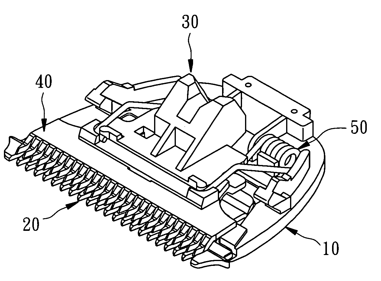
  • Cutter assembly for hair clipper
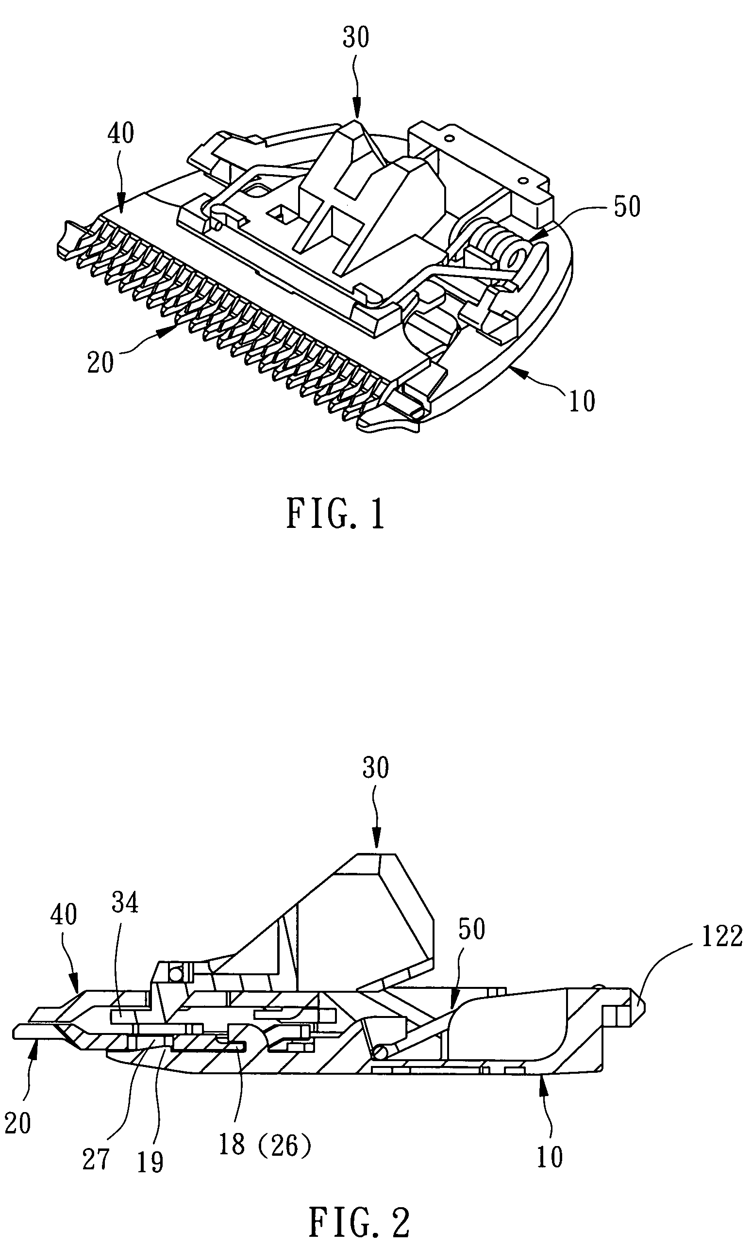
  • Cutter assembly for hair clipper
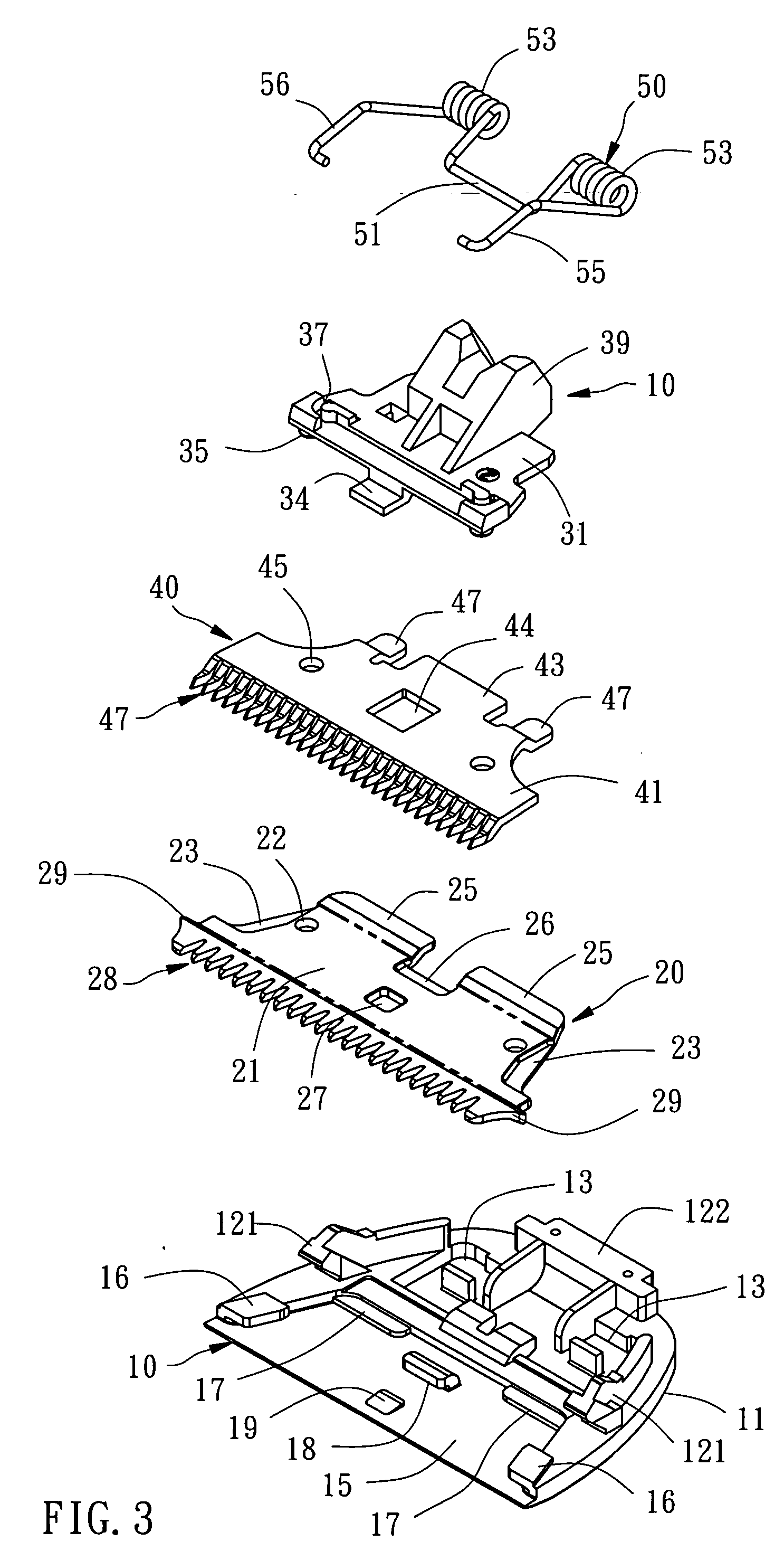
  • Cutter assembly for hair clipper

Examples


Embodiment Construction

[0015] Referring to FIGS. 1˜7, the invention provides a cutter assembly connectable to a clipper body of a hair clipper. The cutter assembly comprises a first cutter holder 10, a first cutter 20, a second cutter holder 30, a second cutter 40, and a spring member 50.

[0016] The first cutter holder 10 comprises a holder base 11, a first mounting portion 121 and a second mounting portion 122 that form a clipper mounting portion, a spring seat 13, a cutter seat 15, two engagement portions 16, two first connecting portions 17 and one second connecting portion 18, and a retainer 19.

[0017] The first cutter 20 is mounted in the first cutter holder 10, comprising a cutter plate 21, two mounting holes 22, two engagement portions 23, two first connecting portions 25, a second connecting portion 26, a retaining portion 27, a notched cutting edge 28, and two flock pushing guides 29. The flock pushing guides 29 are triangular members respectively protruding over the two opposite lateral sides of...


PUM


Abstract

A cutter assembly for hair clipper is disclosed to include a first cutter holder and a first cutter mounted in the first cutter holder, the first cutter having two flock pushing guides at two sides of the cutting edge thereof for guiding out waste cut hairs, and a movable cutter set movable alternatively leftwards and rightwards relative to the first cutter holder and formed of a second cutter holder and a second cutter mounted in the second cutter holder.

Description

BACKGROUND OF THE INVENTION [0001] 1. Field of the Invention [0002] The present invention relates to hair clipper and more particularly to a cutter assembly for hair clipper. [0003] 2. Description of the Related Art [0004] A hair clipper for cutting hair is generally comprised of a clipper body, and a cutter assembly mounted in the clipper body and formed of two cutter sets that are movable relative to each other. According to this design, there is an assembly gap is left between the cutter assembly and the clipper body. This assembly gap may cause the hair to be stretched by the cutter assembly during cutting. Further, waste cut hairs may enter this assembly gap and may be jammed in between parts of the hair clipper, producing a resistance to the movable cutter set. [0005] Further, the parts of the aforesaid conventional hair clipper are expensive to manufacture and complicated to assemble. Therefore, it is desirable to provide a cutter assembly for hair clipper that eliminates the...

Claims


Application Information

Patent Timeline
IPC IPC(8): B26B19/00B26B19/06
CPCB26B19/06
Inventor LIAO, YI-TANG
Owner JENG SHYUAN PRECISION
Learn More