
Umbrella grip attached with a light source

Inactive Publication Date: 2006-02-23
WU HSIEN SAO
View PDF1 Cites 6 Cited by
  • Summary
  • Abstract
  • Description
  • Claims
  • Application Information

AI Technical Summary

Benefits of technology

[0007] Accordingly, the main object of the present invention is to provide an umbrella grip attached with a light source in switch both the power and light source are combined in a housing which is attached to the umbrella grip so as to eliminate the need of electric wiring.
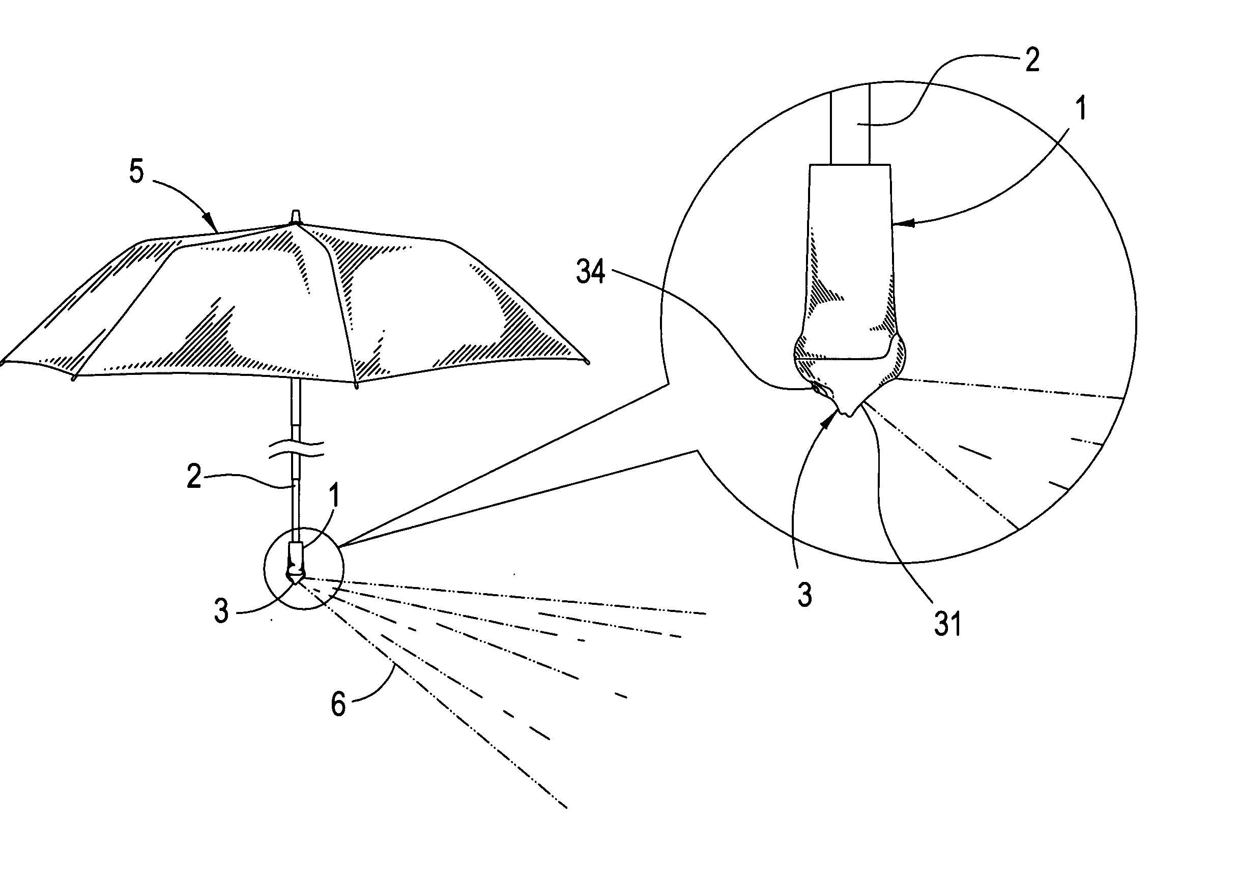
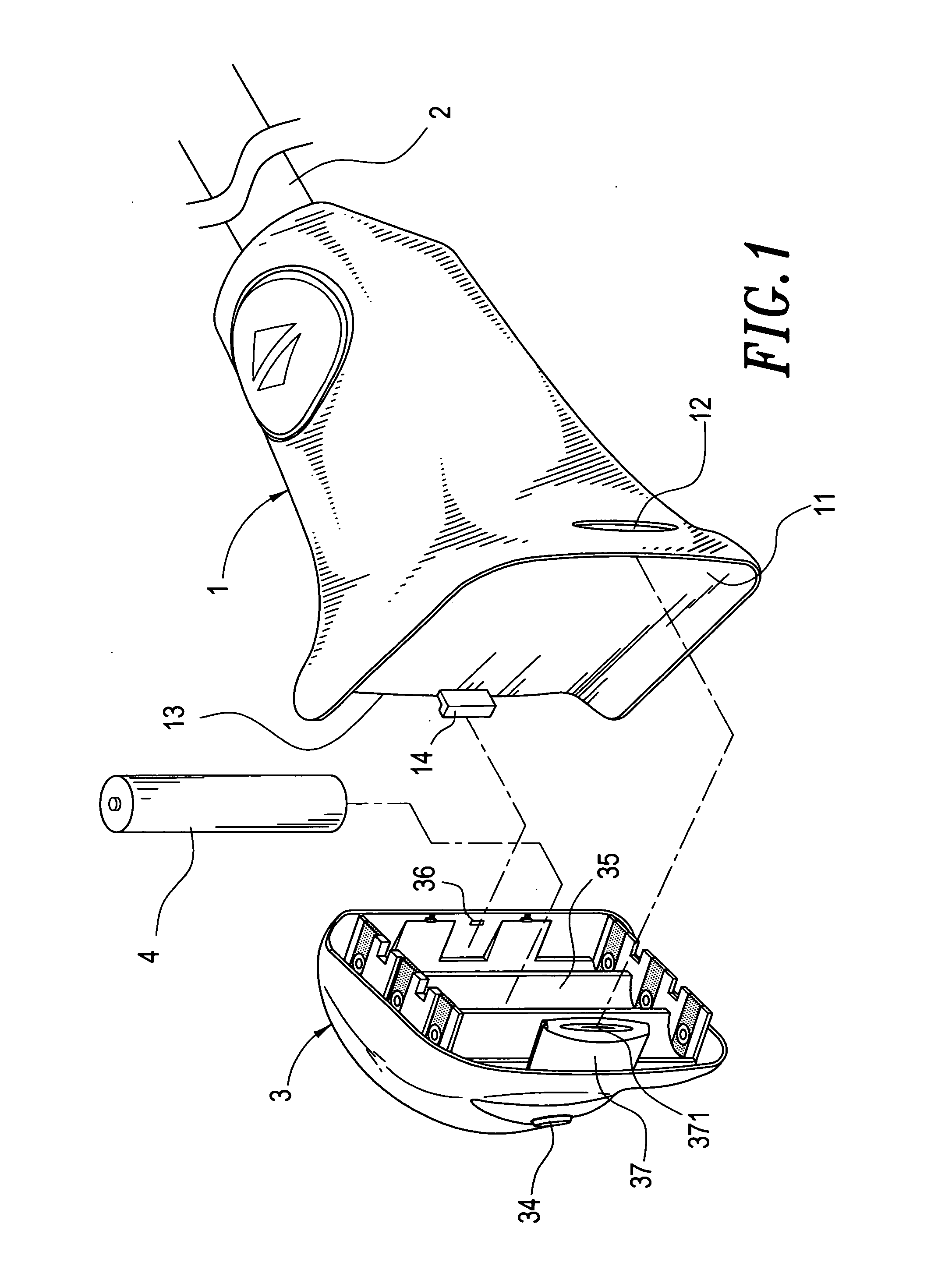
[0009] To achieve the aforementioned objects, the present invention provides a housing for lighting source attached to the bottom of the grip formed at the lower end of the umbrella back bone. The front portion of the housing is formed into a sloped surface serving as a refractor with a transparent window where a high intensity lighting element is installed inside such that the light beam is conducted down and distributed on the ground under to umbrella. A battery box is sandwiched and concealed between the umbrella grip and the housing with a battery unit set in it serving as power supply to the lighting element. With this structure, the electric wiring is no more necessary therefore resulting in saving the production cost and simplifying the assembly of the umbrella attached with a light source according to the present invention.

Problems solved by technology

The light source attached to an umbrella in such manners is disadvantageous that the lamp fails to work in the case the electric conductor laid in the umbrella back bone is disconnected by some accident, besides, such complicated installation cause assembly of an illuminated umbrella cost and time wasting, and light intensity is often practically insufficient if an ordinary miniature incandescent bulb is used.
For these defects noticeable on the prior art, an improvement is seriously required.

Method used


Image

  • Umbrella grip attached with a light source
  • Umbrella grip attached with a light source
  • Umbrella grip attached with a light source

Examples


Embodiment Construction

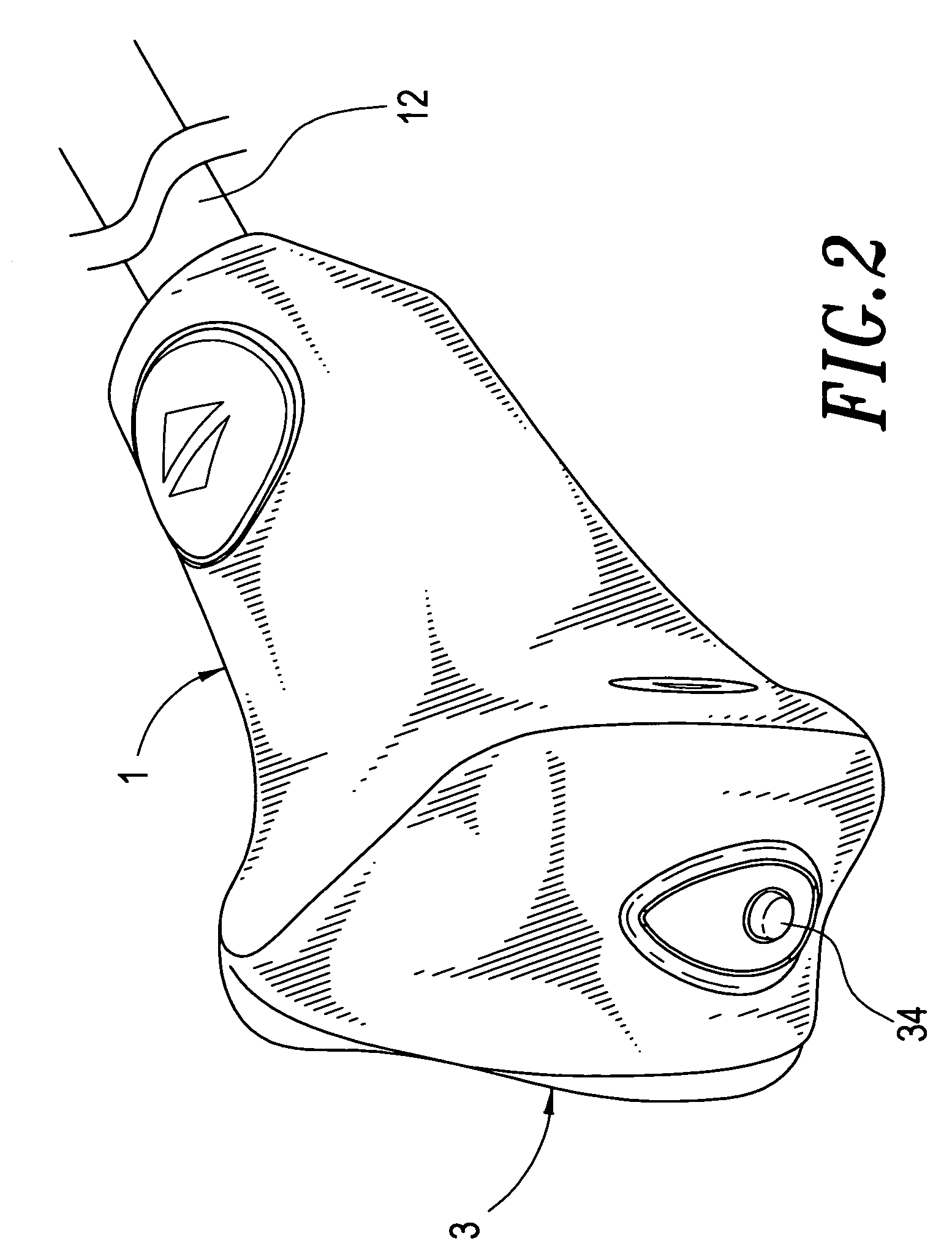
[0015] Referring to FIG. 1 through FIG. 3, the umbrella grip attached with a light source is essentially composed of an umbrella grip 1 and a light source housing 3.

[0016] The umbrella grip 1 is installed at the lower end of an umbrella back bone 2. A chamber 11 formed at the bottom of the grip 1 is provided with a slot 12 at its one side and a port 13 left open at the opposite side, and an approximately 1 shaped hasp 14 is protruded from the center of the port 13.

[0017] The delta shaped housing 3 has a sloped surface 31 with a transparent window 32 formed at its front portion. A high intensity light source 33, or the equivalents is installed in the window 32. A switch 34 is installed at the rear portion of the housing 3 to control on-off of the power supply to the light source 33. A battery unit 4 which serves as a power source of the light source 33, is equipped in a battery box 35 formed at the top portion of the housing 3 and having a stopper 36 provided at its front wall surf...


PUM


Abstract

A light source for an umbrella directly attached to its grip is set forth herein, a light source housing containing a light source, a battery unit, and a light source is engaged to the bottom of the umbrella grip. The battery power is directly supplied to the light source without using the electrical wiring. LED(s), or other high intensity lamps may be employed as the light source. The front portion of the light source housing is formed into a sloped surface serving as a refractor to conduct the light beam downwards and distribute it on the ground under the umbrella so as to assist the umbrella carrier walking at a dark, rainy night securely without the worry of a possible traffic accident.

Description

BACKGROUND OF THE INVENTION [0001] 1. Field of the Invention [0002] The present invention related to an umbrella grip attached with a light source, in particular, a battery energized light source attached beneath the umbrella grip which is used to illuminate the ground under the umbrella without the need of electric wiring in the umbrella. [0003] 2. Description of the Prior Art [0004] In order to assure the pedestrian's traffic security when walking with an umbrella in a rainy night, use of an illuminated umbrella is indeed a good solution. For this, there have been two styles of illuminated umbrella prevailing on the market. One is installing a battery unit in the umbrella grip as a power supply to turn on a lamp equipped somewhere in the transparent umbrella back bone so as to perform a warning effect in the dark, rainy night, on the other hand the battery unit is in stalled in the grip, and an ornamental lamp is provided on top of the back bone. Both styles of illuminated umbrell...

Claims


Application Information

Patent Timeline
IPC IPC(8): A45B3/02
CPCY10S362/80A45B3/04
Inventor WU, HSIEN-SAO
Owner WU HSIEN SAO
Learn More