
Pressure exchange apparatus with dynamic sealing mechanism

a technology of dynamic sealing and pressure exchange apparatus, which is applied in the direction of rotary piston liquid engine, wind motor with perpendicular air flow, water/sewage treatment, etc., and can solve the problems of high value of pressure energy that it contains, long and trouble-free operation life, and high energy consumption of continuous flow operation

Inactive Publication Date: 2006-02-23
SHUMWAY SCOTT
View PDF0 Cites 30 Cited by
  • Summary
  • Abstract
  • Description
  • Claims
  • Application Information

AI Technical Summary

Benefits of technology

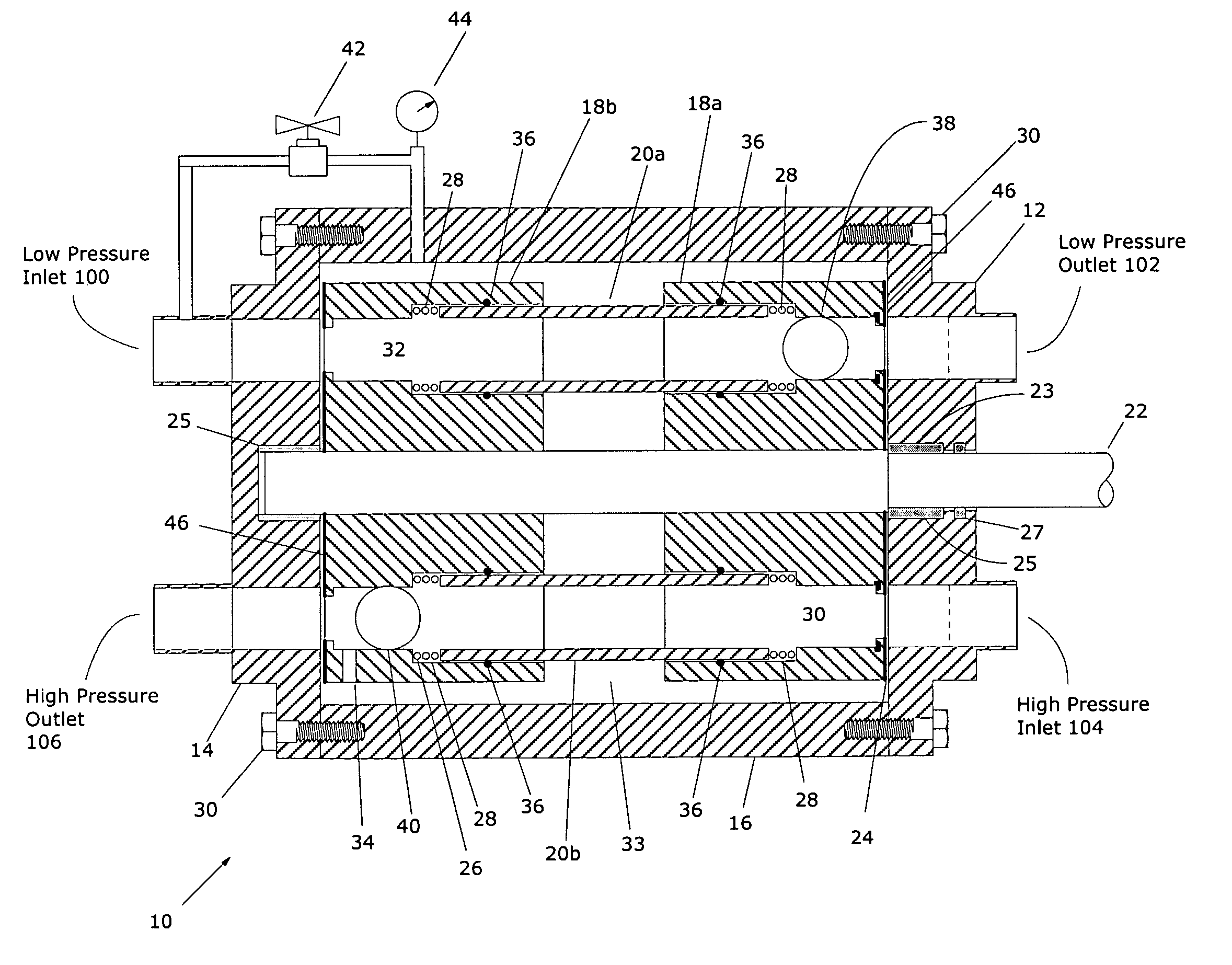
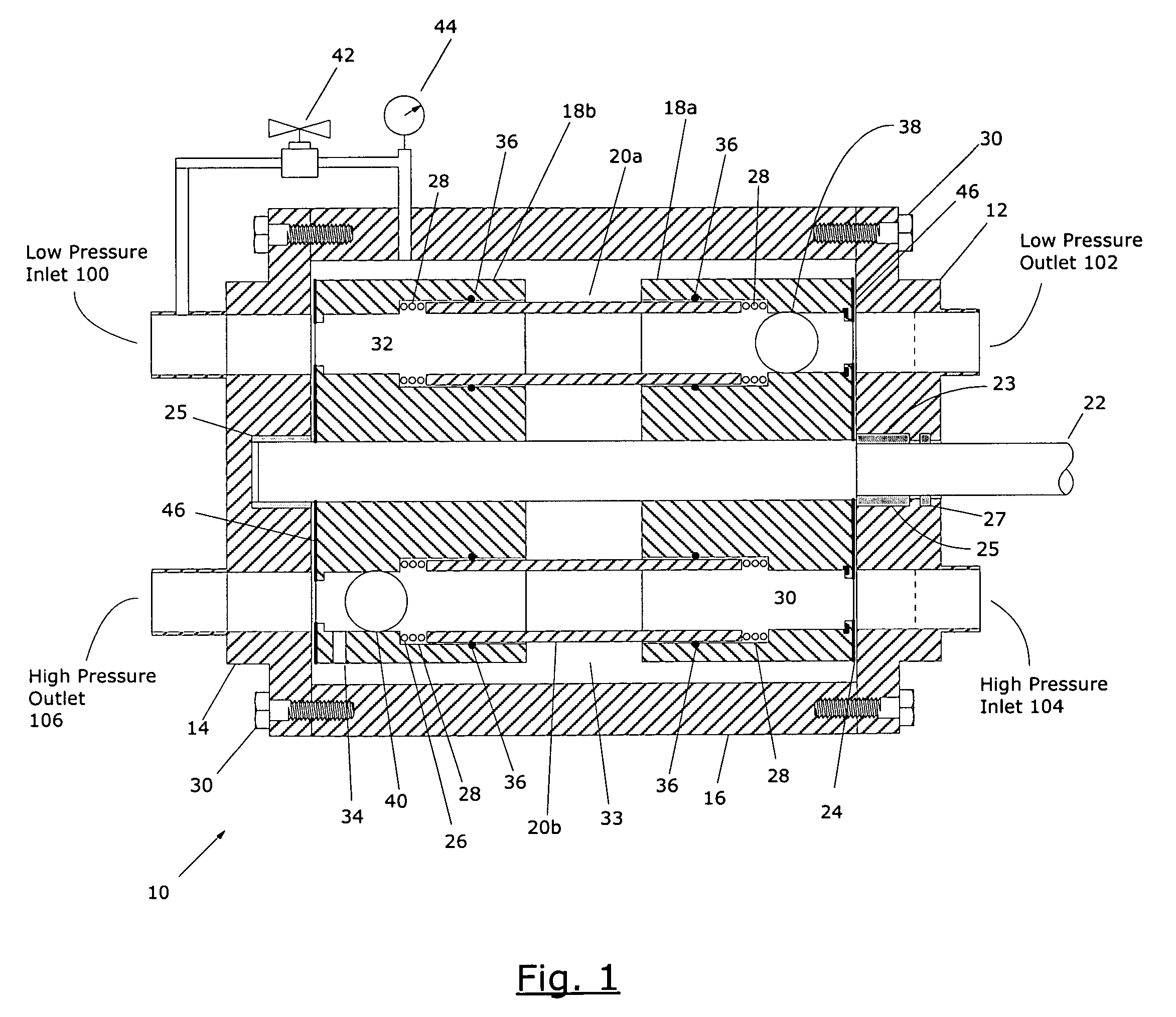
[0017] In a further aspect of the invention, a pressure exchange apparatus for transferring the energy of pressurization between two fluids is provided, wherein one fluid is at a relatively higher pressure than the other. A first rotatably mounted rotor having a pair of spaced apart planar end faces, having at least one bore extending axially therethrough with each of the bores having an opening at each end thereof with the openings located in the planar end faces. A second rotatably mounted rotor being spaced apart from and coaxially aligned with the first rotor, the second rotor having a pair of spaced apart planar end faces, having at least one bore extending axially therethrough with each of the bores having an opening at each end thereof with the openings located in the planar end faces. A pair of closure plates rigidly affixed in close proximity to a respective end face of the first rotor and the second rotor. The closure plates slidingly and sealingly engaging the respective end face, and each of the closure plate having at least one fluid inlet passageway and at least one fluid discharge passageway, the passageways being positioned so that a fluid inlet passageway in one of the closure plates is aligned with the bore in the rotors at such time during the rotation of the rotors as a fluid discharge passageway in the other closure plates is

Problems solved by technology

The device employed for achieving this highly efficient transfer has a long and trouble free operating life which is not interrupted by the plugging and fouling of valves, or the binding or freezing of sliding pistons or the like.
For this reason, continuous flow operation requires much greater energy consumption than non-flow pressurization.
While the high pressure brine is no longer useful in this process as a fluid, the pressure energy that it contains has high value.
The movement of the separation device is limited due to the use of a seat at each end of the passages.
The seats cause a reduction in cross-area of the bores and are susceptible to wear and eventual failure.
Referring to FIG. 3 which shows a cross-section of the prior art exchanger, a major drawback of the prior art is the reduction in sealing surface-area between the inlet and outlet ports.
Leakage between these two ports results in reduced efficiency of the pressure exchanger, and as the tight tolerances of the mechanical components begin to wear, leakage between the ports will only increase and require costly maintenance as shown in FIG. 3.
Due however to the obvious drawbacks of this approach, the seals eventually wear out and or the springs degrade overtime, both of which require expensive downtime and repair.
A seal with intermittent sealing capability is undesirable since leakage of high pressure fluid to the low pressure conduit represents a reduction in efficiency of the device.

Method used


Image

  • Pressure exchange apparatus with dynamic sealing mechanism
  • Pressure exchange apparatus with dynamic sealing mechanism
  • Pressure exchange apparatus with dynamic sealing mechanism

Examples


Embodiment Construction

[0022] The following detailed description is of the best currently contemplated modes of carrying out the invention. The description is not to be taken in a limiting sense, but is made merely for the purpose of illustrating the general principles of the invention, since the scope of the invention is best defined by the appended claims.

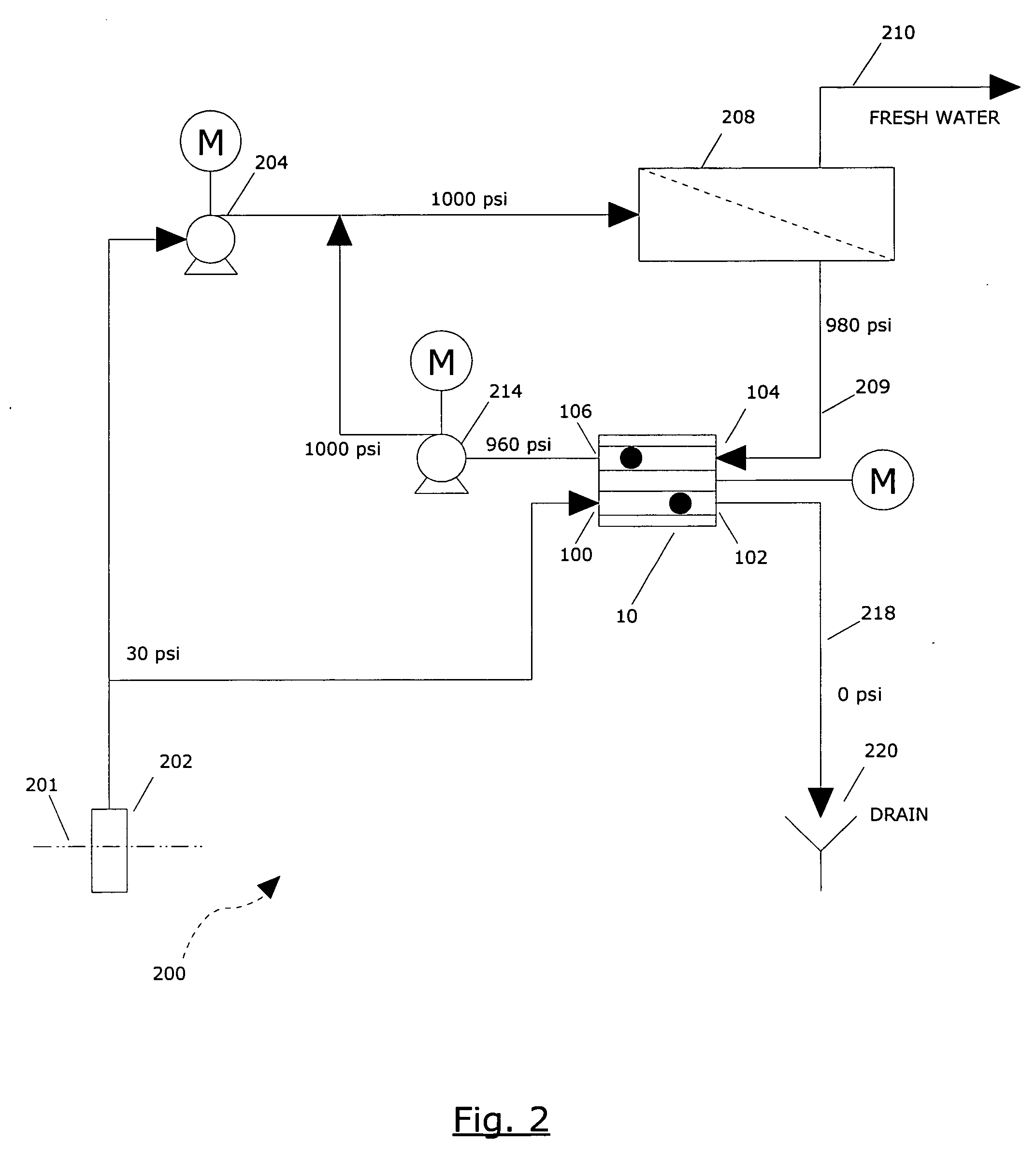
[0023] Referring first to FIG. 2, which depicts a process flow diagram for a salt water filtration system 200 that uses a reverse osmosis process for the production of potable water which comprises a pressure exchange device 10 in accordance with the present invention.

[0024] A salt water reservoir 201 provides a supply of salt water which is pumped to a high pressure pump 204 by reservoir pump 202. Typically the reservoir pump 202 supplies salt water to both the high pressure pump 202 and the pressure exchange device 10 at approximately 30 psi pressure at approximately equal flow rates. The high pressure pump 204 boosts the pressure to approximately ...


PUM

PropertyMeasurementUnit
Forceaaaaaaaaaa
Pressureaaaaaaaaaa
Displacementaaaaaaaaaa

Abstract

A pressure exchange device is provided that utilizes a rotor assembly inside a housing to transfer the pressure of a fluid from one high pressure fluid to another low pressure fluid. The housing may comprise a pressurized fluid contained therein to provide a sealing force to reduce fluid leakage between the spinning rotors and the housing. The sealing force and wear characteristics may be controlled to reduce leakage and wear of the pressure exchange device. The rotor assembly may be driven in either direction and the high pressure ports may be switched with the low pressure ports if desired.

Description

BACKGROUND OF THE INVENTION [0001] This invention relates to pressure exchangers for transfer of energy from one liquid flow to another. More specifically, this invention relates to pressure exchangers for the transfer of energy from one liquid stream to another using a rotating split rotor exhibiting enhanced / proportional sealing and wear adjustment characteristics. [0002] The present invention provides a device which can be appropriately described as an engine for exchanging pressure energy between relatively high and relatively low pressure fluid systems, which the term fluid being defined here as including gases, liquids and pumpable mixtures of liquids and solids. The engine for pressure energy exchange of the present invention is a highly efficient device with well over 90% of the energy of pressurization in a pressurized fluid system being transferred to a fluid system at a lower pressure. The device employed for achieving this highly efficient transfer has a long and trouble...

Claims


Application Information

Patent Timeline
IPC IPC(8): B01D29/88F04F99/00
CPCB01D61/06F04F13/00F04B9/1176C02F2103/08Y02A20/131
Inventor SHUMWAY, SCOTT
Owner SHUMWAY SCOTT
Learn More