Attachment system for an electrical device for installation in aircraft cabins

Inactive Publication Date: 2006-02-23
AIRBUS OPERATIONS GMBH
View PDF5 Cites 0 Cited by
  • Summary
  • Abstract
  • Description
  • Claims
  • Application Information

AI Technical Summary

Benefits of technology

[0015] In an exemplary embodiment of the present invention an attachment system is based on a two-component design of the electrical devices to be installed. One component comprises a base component that is to be installed so as to be fixed, which base component can be affixed with normal attachment means to a place of installation, for example to a cabin wall. This base component comprises a connector unit which comprises an adequate number of poles to be able to accommodate all supply lines required for supplying the electrical device to be installed. In this way all supply lines can end at the connector unit. The second component comprises an actual housing of the electrical device to be installed, at which component there is a connector unit that is complementary to the connector unit of the base component. Both components comprise attachment means which make possible fast interconnection of the two components in that the attachment means can be made to engage each other. Various forms of quick-acting closures and spring-loaded disconnecting mechanisms are suitable as attachment means.
[0019] Particularly simple and convenient installation of the electrical device may result if the housing connector unit comprises a protruding spout which when the complementary connector units are plugged into each other during installation may cause guidance of the movement of the housing component in the direction towards the base component, in the installed state may form an end stop, and telescopically may enclose the supply connector unit.
[0021] In order to increase the convenience during service and maintenance activities it may be advantageous if the swivellable claws in the installed state incompletely grip the stud bolts from the back, and if during undoing of the housing component above a specified pull-off force, automatic unlocking of the connection between stud bolts and claws may take place. The required pull-off force may be adjusted without any problem by way of the geometry of the swivellable claws and the spring constant of the spring, which keeps the claws engaged with the stud bolts. Consequently, in this way too, adaptation of the attachment system to the sometimes considerable acceleration that can occur in aircraft operation may take place without compromising safety.
[0023] In many applications it may be advantageous if the complementary connector units are designed in two rows and incorporate at least eight poles. Larger numbers of poles may be implemented without any problem. Apart from simple connection of multi-pole consumers this may open up an advantageous robust connector geometry which may even suitable for accommodating loads, and which may support the already mentioned guided movement during attachment of the electric device in a way that there may be essentially no need to provide further guiding means.
[0024] Because of the securely installed connectors not only in the device but also in the counterpart it may be possible to implement a fixed routing of lines. The hitherto required overlength of the connection cables for connecting the electrical devices may become superfluous as a result of this. Any uncontrolled line routing, which previously could result in chafing spots, may thus be prevented. There may no longer be a need to provide mechanical protection against chafing.
[0026] As a result of the principle according to the invention, which may involve mechanical and electrical coupling at the same time, the production effort may clearly reduced both as far as the installation times and any remedial work that may be needed is concerned. Uniformly two simply-to-prepare and lightweight components may to be installed, which may result in savings of weight and expenditure.

Problems solved by technology

The installation effort essentially arises from the necessary connection to electrical supply lines and from attachment of the device at the intended installation location.
The phase of cabin fitout requires considerable installation effort because the devices have to be attached at the intended installation location, for example by means of screw connections, and by the allocation and connection of numerous (mostly one-pole) plug-type connections for electrically connecting the devices.
This superfluous line part carries the danger of uncontrolled movement and uncertain line routing of the supply lines, as a result of which the danger of chafing arises.
Maintenance measures require considerable installation effort because even in the case of exchanging individual components, deinstallation and renewed connection of the device may become necessary.
In the context of renewed separation and connection of the individual plug-type connections, any maintenance measure entails a danger of mixing up the connectors, which requires additional troubleshooting and remedial action.
Especially in the case of exit signs this is an additional disadvantage in that exchange of these safety-relevant components must be able to be carried out practically anywhere.
Adapting the electrical devices to be installed to the requirements of the place of installation can result in a considerable increase in the weight of the devices when installation is to take place by integration in other assemblies and when such integration requires adaptive constructive measures.
Extensive integration also increases production costs.

Method used


Image

  • Attachment system for an electrical device for installation in aircraft cabins
  • Attachment system for an electrical device for installation in aircraft cabins
  • Attachment system for an electrical device for installation in aircraft cabins

Examples


Embodiment Construction

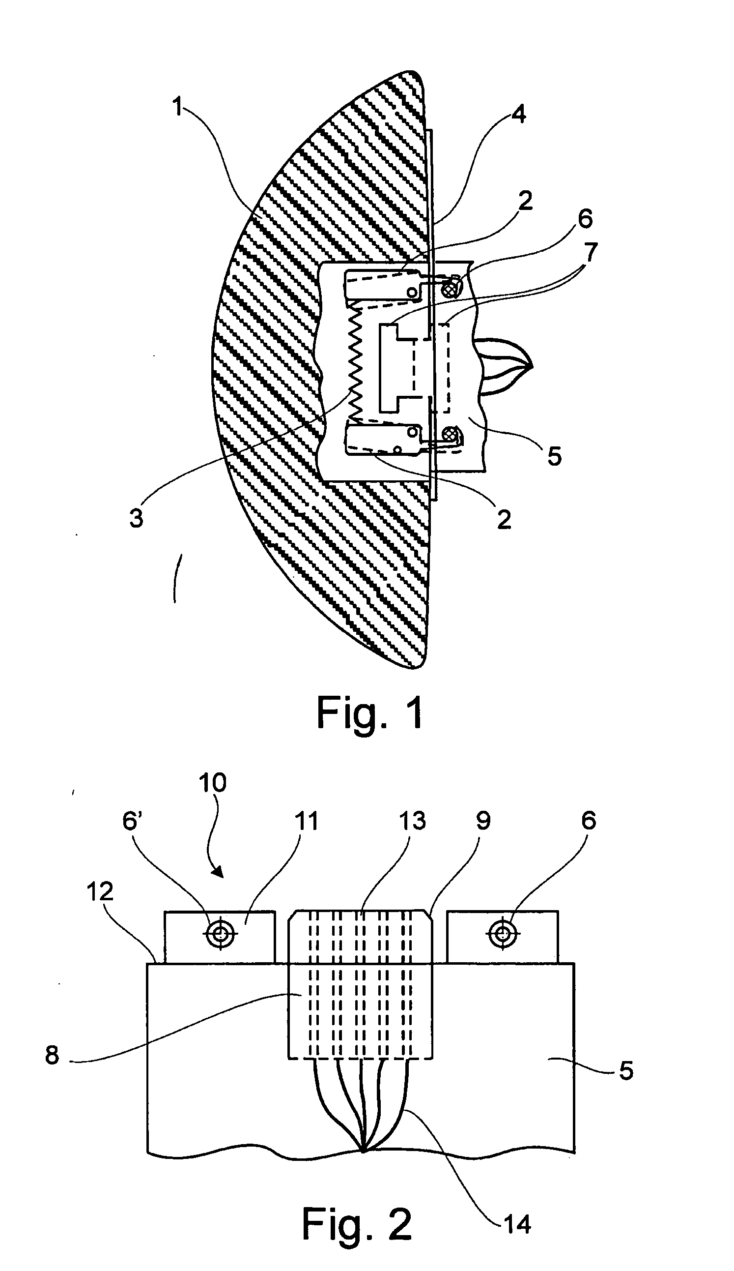
[0037]FIG. 1. The interior of a dome-shaped housing 1 of an exit sign comprises swivellable claws 2 which can be deflected against the restoring force of a stretched spring 3. At its margin a base component 5, installed to the cabin wall 4 so as to be fixed, comprises stud bolts 6, which are gripped from the back by the swivellable claws 2. In the centre region there is an interconnected pair of complementary connector units 7, which ensures the electrical connection between the base component and the housing component.

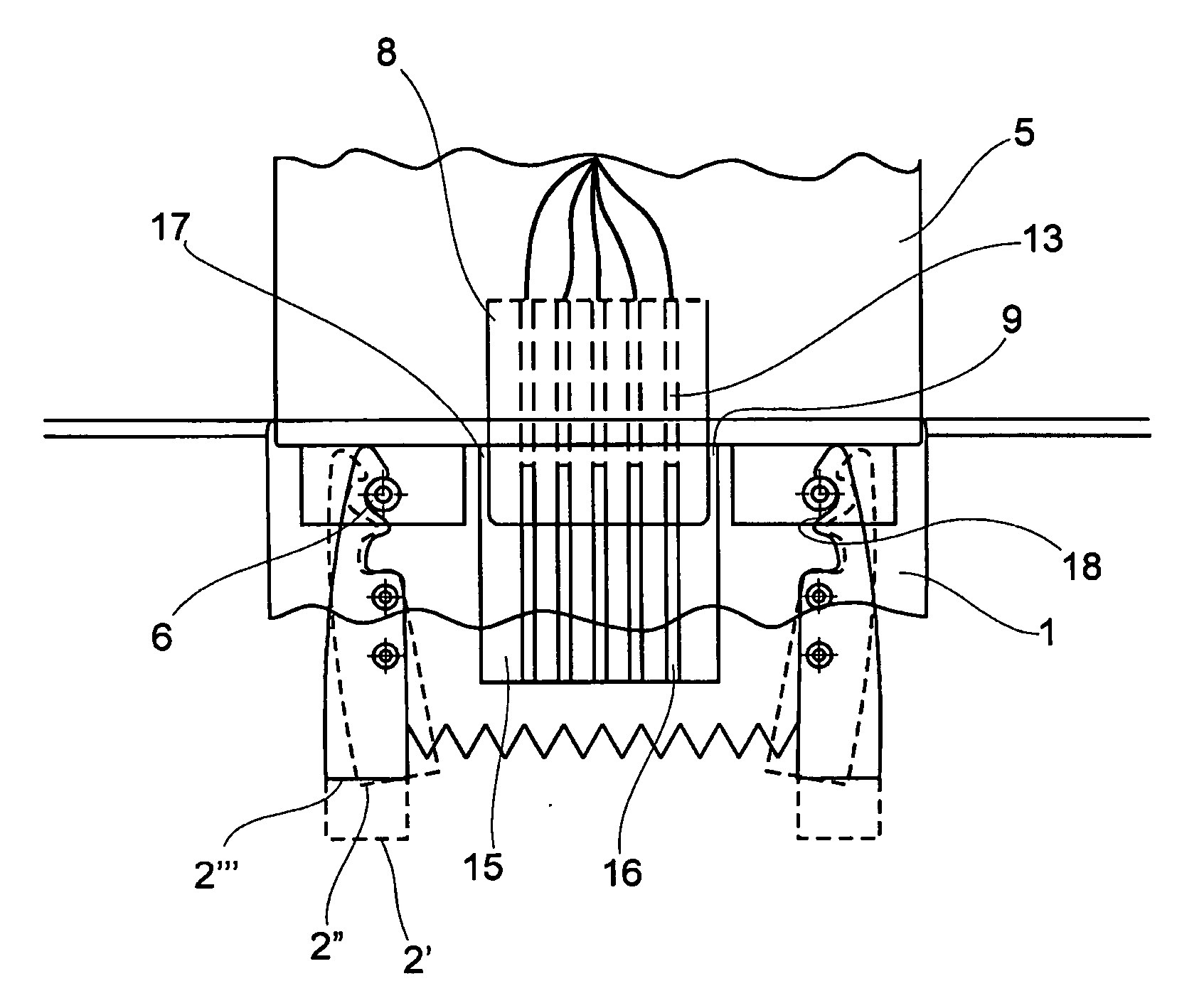
[0038]FIG. 2 shows a lateral view of a section of a base component 5 according to the invention, with a multi-pole supply connector unit 8, prepared for connection to various electrical supply lines, as a base, with a phase 9 to facilitate installation. The supply connector unit 8 is a ten-pole design. Nine poles are assigned. On the side of the supply connector unit 8 stud bolts 6 are connected to the base component 5, wherein the axes of said stud bolts 6 extend so...


PUM


Abstract

The invention relates to an attachment system for an electrical device for installation in aircraft cabins, comprising a base component to be installed so as to be fixed; with a multi-pole supply connector unit, prepared for connection to various electrical supply lines, as a base; attachment means affixed to the base component; a housing component that is to be detachably attached, which is designed for accommodating the electrical device with at least one electrical consumer; a housing connector unit connected to the electrical consumer, of which there is at least one, by way of electrical lines, which housing connector unit is affixed to the housing component so as to be complementary to the supply connector unit; and attachment means affixed to the housing component, which attachment means automatically connect to the attachment means affixed to the base component when the complementary connector units are plugged into each other.

Description

REFERENCE TO RELATED APPLICATIONS [0001] This application claims the benefit of the filing date of U.S. Provisional Patent Application No. 60 / 602,373 filed Aug. 18, 2005, and of German Patent Application No. 10 2004 040 029.6 filed Aug. 18, 2005, the disclosures of which are hereby incorporated herein by reference.FIELD OF THE INVENTION [0002] The present invention relates to an attachment system for an electrical device for installation in aircraft cabins. Particularly, the invention relates to such attachment systems that can be used wherever, during fitting of interior equipment in aircraft, initially quick installation and later simple, safe and quick exchangeability of the installed devices in the case of maintenance are desired. TECHNOLOGICAL BACKGROUND [0003] Interior equipements of aircraft include numerous electrical devices that have to be fixed into place, some of which devices are provided as prefabricated units. The installation effort essentially arises from the necess...

Claims


Application Information

Patent Timeline
IPC IPC(8): H05K3/30
CPCH01R13/6275
Inventor WUSSOW, BURGHARDPISKRZYNSKI, UWE
Owner AIRBUS OPERATIONS GMBH
Why Eureka
Try Eureka