
Implant assembly and method for use in an internal structure stabilization system

a technology of internal structure and stabilization system, which is applied in the direction of ligaments, instruments, gearing, etc., can solve the problems of reducing the height of the intervertebral disc, reducing the height of the disc, so as to achieve the effect of locking out the conical freedom of the anchor

Active Publication Date: 2006-02-16
THEKEN SPINE
View PDF98 Cites 523 Cited by
  • Summary
  • Abstract
  • Description
  • Claims
  • Application Information

AI Technical Summary

Benefits of technology

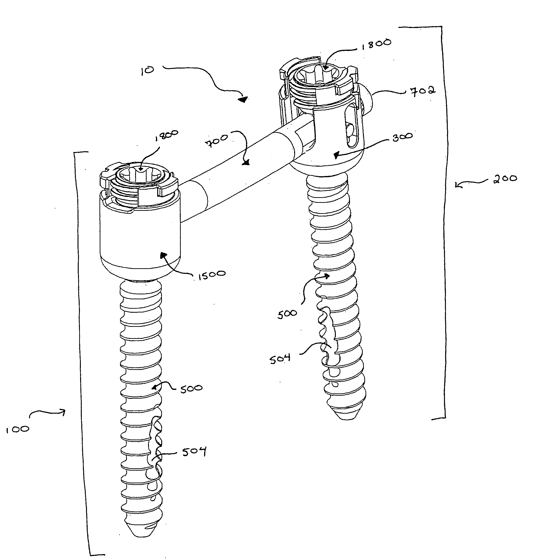
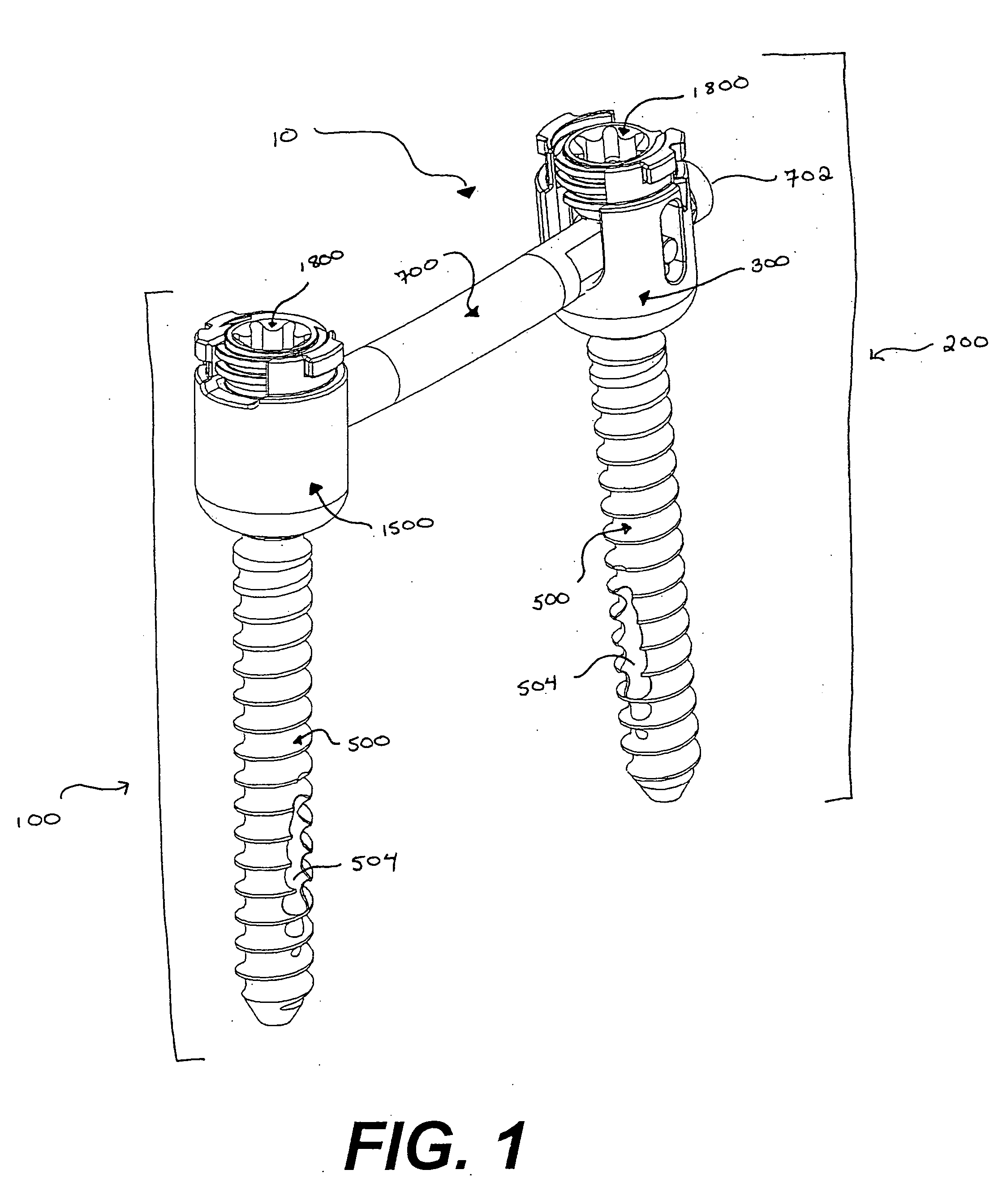
[0018] Further, a locking cap for use with the stabilization assembly is described. The locking cap formed by a locking ring which is threaded into a poly-axial head, the locking ring operable to cause the poly-axial head and anchor to assume a fixed, rigid relationship with one another, effectively locking out the conical freedom of the anchor with respect to the head while still allowing the connector to slide within the slide ring. The compression cap threads into the locking ring and acts to compress the connector and slide ring locking the connector into position, and preventing the connector from sliding within the slide ring.

Problems solved by technology

Over time, or because of accidents, the intervertebral discs loose height, become cracked, dehydrated, or herniated.
The result is that the disc height is reduced leading to compression of the nerve bundles, causing pain and in some cases damage to the nerves.
One problem when connecting the braces to the anchors is to position the braces in place as quickly as possible and without doing more damage to the surrounding tissue and muscle of the patient as is absolutely necessary.
It is difficult for the physician to know the exact orientation of the brace and even to know for certain when the brace ends have been properly positioned.
Another problem with both of the approach discussed above, is that the braces must be made significantly longer than the distance between the pedicle screws to allow for proper attachment of the brace ends to the screws.
If this trajectory is not established properly, the brace would have to pass through tissue or would be blocked by bone.
Also, the design of the brace necessitates a separate incision in the back of the patient, and the learning curve for manipulation the insertion device of the '929 patent is difficult.
Proper positioning of the rod ends is difficult, and requires repeated use of fluoroscopy to insure that the rod is fully seated and in a correct position.
If the rod is not fully seated, the construct will not assemble correctly and will most likely fail.
Further, the failure of the construct will most likely not be immediately apparent.

Method used


Image

  • Implant assembly and method for use in an internal structure stabilization system
  • Implant assembly and method for use in an internal structure stabilization system
  • Implant assembly and method for use in an internal structure stabilization system

Examples


Embodiment Construction

[0102] To better understand the devices, assemblies, tools, and methods described below, and understanding of the procedure through which the back stabilization of the present invention is placed into the vertebrae of a patient is required. Reference is made to the figure numbers where specific embodiments of the devices, assemblies, tools and methods are described in greater detail to aid in the understanding of those particular items.

[0103] An operation to insert a pedicle screw assembly into a patient's back to immobilize certain vertebrae in order to allow bone grafts to ultimately fuse those vertebrae begins with the surgeon inserting a standard bone biopsy needle into the pedicle of a first vertebra and using the bone biopsy needle to place a guide wire where the first pedicle screw should be inserted. Using the guide wire, progressively larger tissue expanders are inserted into the patient to expand, or dilate, the incision to the size necessary to accommodate the instrument...


PUM


Abstract

A stabilization assembly is described that stabilizes bony structures such as vertebrae. The stabilization assembly is partially formed by a poly-axial assembly which includes an anchor connected to a poly axial connector assembly head, where the poly-axial connector-assembly head includes a slide ring mounted in the head and a connector mounted in the slide ring. The slide ring allows the connector to move between an upright and a horizontal position relative to the poly-axial connector-assembly head. In the upright position the connector engages with a drive mechanism on the anchor for inserting the anchor into a pedicle. In the horizontal position the connector can engage a poly-axial connector capturing assembly which is the second piece included in the stabilization assembly. An end of the connector engages with a poly-axial connector-capturing head which is connected another anchor mounted in a second pedicle. Once the connector is captured by the poly-axial connector-capturing assembly, the stabilization system is made rigid by installing locking caps in the poly-axial heads.

Description

CROSS-REFERENCE TO RELATED APPLICATIONS [0001] This application is a Utility Patent Application related to Utility patent application Ser. No. 10 / 690,211, filed Oct. 21, 2003, entitled “SYSTEM AND METHOD FOR STABILIZATION OF INTERNAL STRUCTURES,” the disclosure of which is hereby incorporated herein by reference.TECHNICAL FIELD [0002] This invention relates to bone stabilization systems, and more particularly to implant assemblies and their components for stabilizing bony structures such as vertebrae. BACKGROUND OF THE INVENTION [0003] The human spine provides a vast array of functions, many of which are mechanical in nature. The spine is constructed to allow nerves from the brain to pass to various portions of the middle and lower body. These nerves, typically called the spinal cord, are located in a region within the spine called the spinal canal. Various nerve bundles emerge from the spine at different locations along the lateral length of the spine. In a healthy spine, these ner...

Claims


Application Information

Patent Timeline
IPC IPC(8): A61F2/30A61B17/70A61B17/88
CPCA61B5/103Y10T74/22A61B5/4504A61B17/1604A61B17/1655A61B17/1757A61B17/320016A61B17/3417A61B17/3421A61B17/3468A61B17/7002A61B17/7005A61B17/701A61B17/7011A61B17/7032A61B17/7037A61B17/7038A61B17/704A61B17/7082A61B17/7085A61B17/7091A61B2017/320044A61B2019/461A61B2019/467A61B5/6878A61B5/6882A61B5/107A61B2090/067A61B2090/061
Inventor SPITLER, JAMESSCHORER, SCOTTCOLLERAN, DENNIS
Owner THEKEN SPINE
Learn More