
Roof vent

a technology for roof vents and ridge vents, which is applied in ventilation systems, lighting and heating apparatus, heating types, etc., can solve the problems of increasing snow melt, leaking through roof decks and into residences, and affecting so as to improve the drafting efficiency of ridge vents and improve the effect of roof venting

Inactive Publication Date: 2006-02-16
FARR WILLIAM E +1
View PDF2 Cites 15 Cited by
  • Summary
  • Abstract
  • Description
  • Claims
  • Application Information

AI Technical Summary

Benefits of technology

[0014] The present invention is comprised of a roof vent with an extended portion that exceeds anticipated snow loads in Northern climates. More particularly, the present invention comprises a collection part that compatibly connects to a through hole in a roof construction or engages with an existing roof vent, and which provides an exhaust part that extends well above anticipated snow loads and which provides increased drafting for the exhausting of air flows within a roof system.
[0016] The present invention also comprises an improvement in roof venting by increasing the drafting efficiency of ridge venting.

Problems solved by technology

Roof venting is an issue more for colder climates owing to the potential for damage when snow loading occurs.
Damage results from the situation where a poorly ventilated roof is allowed to trap heat thereby melting some of the snow residing on the roof itself.
Once the ice starts to pile up in this manner, it can act like a dam and cause subsequent snow melt to accumulate in greater and greater quantities.
The resulting water flows will seek the avenue of least resistance which in some cases the penetration of the roofing system (typically shingles) which leads to leaking through the roof deck and into the residence.
Additionally, the water that pools during these events is subject to refreezing and if this happens it will expand.
Water that is trapped in this fashion, creates a great deal of damage to roof systems when refrozen since it will fracture, or separate, or otherwise disrupt the protection afforded by the roofing system, again leading to leakage.
However, the implementation of insulation, even in applications where it is very efficient in retarding heat loss, has not been able to completely solve the historic ice buildup problems associated with modern roofing.
Notwithstanding the success that the roof vents of various types have enjoyed with respect to reducing damage during periods of snow loads, there are occasions when this function breaks down.

Method used


Image

  • Roof vent
  • Roof vent
  • Roof vent

Examples


Embodiment Construction

[0030] A new roof vent in accordance with the present invention overcomes the problems associated with roof venting that is rendered ineffective or totally useless in the face of substantial snow loads. While it should be appreciated that the teachings of the present invention are applicable to many types of roof vents, the particular type of venting design used to illustrate the present invention will be the ridge type ventilation. Ridge vents can be used on different roof types as well, including gable roofs, hip roofs, gambrel roof, and combinations of these.

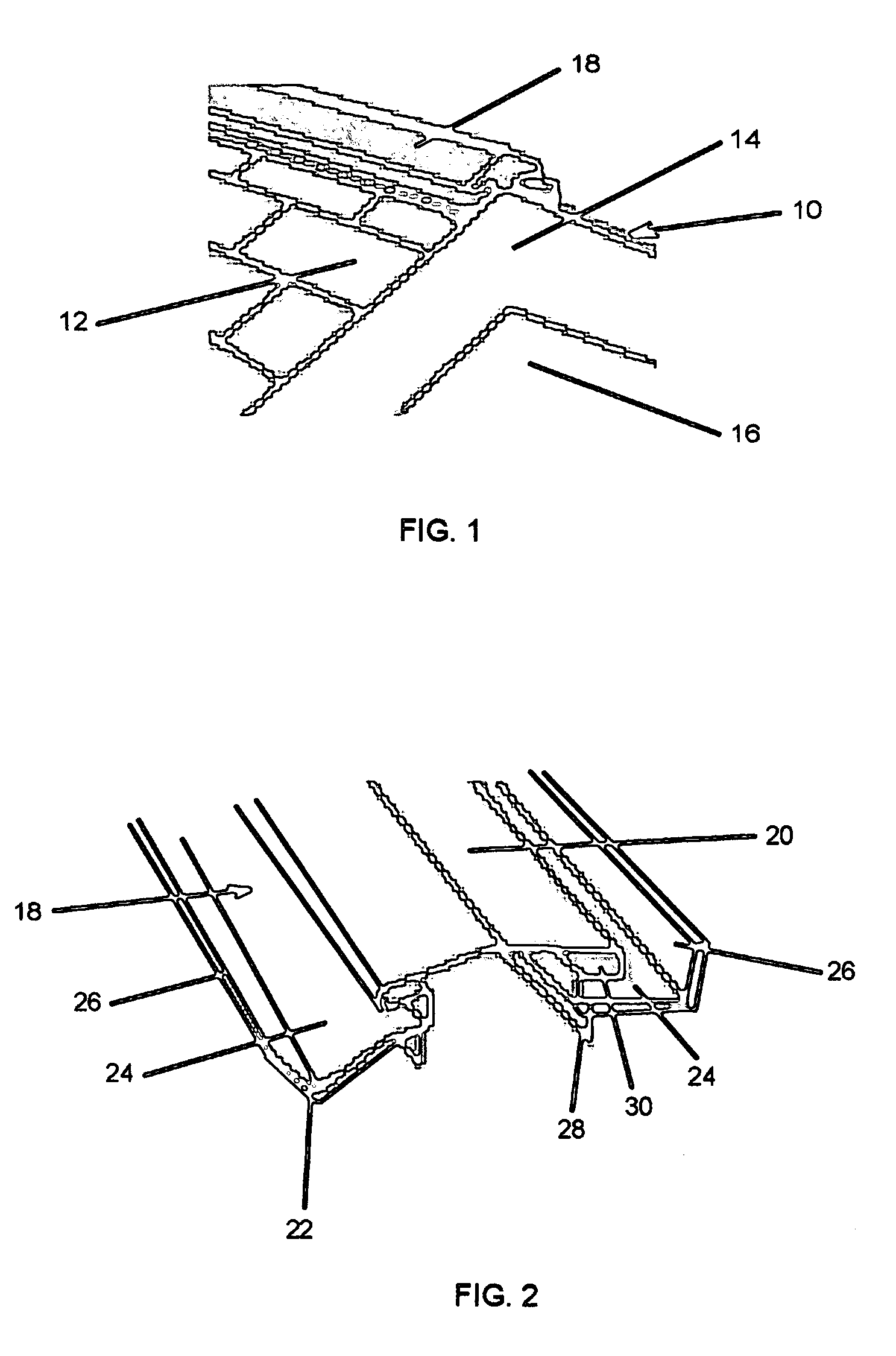
[0031] Turning to FIG. 1, a roof ventilation system of the prior art is shown as installed on roof 10, in this case a gable roof, which includes shingles 12, roof peak 14, sidewall 16 and ridge vent 18. As the name implies, the ridge vent is located on the ridge line formed at the top of the conventional style gable roof design. There is some natural symmetry in the appearance of the ridge vent since it is outwardly shaped w...


PUM


Abstract

A novel roof vent in accordance with the present invention, utilizes a vent pipe communicating with a shroud, where the shroud compatibly fits over a ridge vent on a roof. The vent pipe is extended above the roof, sufficiently so as to rise above the anticipated level of snow load that may be experienced in the locale of the application. The roof vent of the preferred embodiment includes an apron that adjustably fits the roof pitch of the installation and further includes a ridge vent cutout for compatibly fitting over the ridge vent. In one version of the present invention, cosmetic dress may be used to allow the roof vent to blend with architectural requirements without impacting the functionality of the roof vent operation.

Description

CROSS REFERENCE TO RELATED APPLICATIONS [0001] The present application is related to a Provisional Patent Application, No. 60 / 601,839, filed Aug. 16, 2004.STATEMENT REGARDING FEDERALLY SPONSORED RESEARCH OR DEVELOPMENT [0002] Not applicable. BACKGROUND OF THE INVENTION [0003] The present invention relates to roof vents, more specifically, roof vents that remain functional during periods of substantial snow loads. [0004] Roof venting is an issue more for colder climates owing to the potential for damage when snow loading occurs. Damage results from the situation where a poorly ventilated roof is allowed to trap heat thereby melting some of the snow residing on the roof itself. Snow melt will have a tendency to refreeze at times, especially as it migrates and accumulates near the lower roof edges. Once the ice starts to pile up in this manner, it can act like a dam and cause subsequent snow melt to accumulate in greater and greater quantities. The resulting water flows will seek the a...

Claims


Application Information

Patent Timeline
IPC IPC(8): F24F7/02
CPCF24F7/02E04D13/174
Inventor FARR, WILLIAM E.FIELDS, JAMES ARTHUR
Owner FARR WILLIAM E
Learn More