
Gas turbine and gas turbine cooling method

Active Publication Date: 2006-02-16
MITSUBISHI POWER LTD
View PDF22 Cites 18 Cited by
  • Summary
  • Abstract
  • Description
  • Claims
  • Application Information

AI Technical Summary

Benefits of technology

[0007] An object of the present invention is to suppress a reduction in the thermal efficiency of a gas turbine attributable to a leak of the sealing air, which is supplied to the wheel space on the upstream side, from there toward the wheel space on the downstream side.
[0009] With the present invention, a reduction in the thermal efficiency of the gas turbine can be suppressed which is attributable to a leak of the sealing air supplied to a wheel space on the upstream side from there toward a wheel space on the downstream side.

Problems solved by technology

However, when prestress is applied to the diaphragm hook as disclosed in JP-B-62-37204, this may cause a deterioration of materials.
More specifically, temperatures of gas turbine components change from the normal room temperature to a level of 400-500° C. depending on an operating state, and such a large temperature change raises a possibility that the diaphragm hook may be subjected to an excessive load.
On the other hand, if the contact between the diaphragm hook and the nozzle vane hook is insufficient, there arise a possibility that most of the sealing air in the cavity may leak to the wheel space on the downstream side where the pressure is relatively low.

Method used


Image

  • Gas turbine and gas turbine cooling method
  • Gas turbine and gas turbine cooling method
  • Gas turbine and gas turbine cooling method

Examples


first embodiment

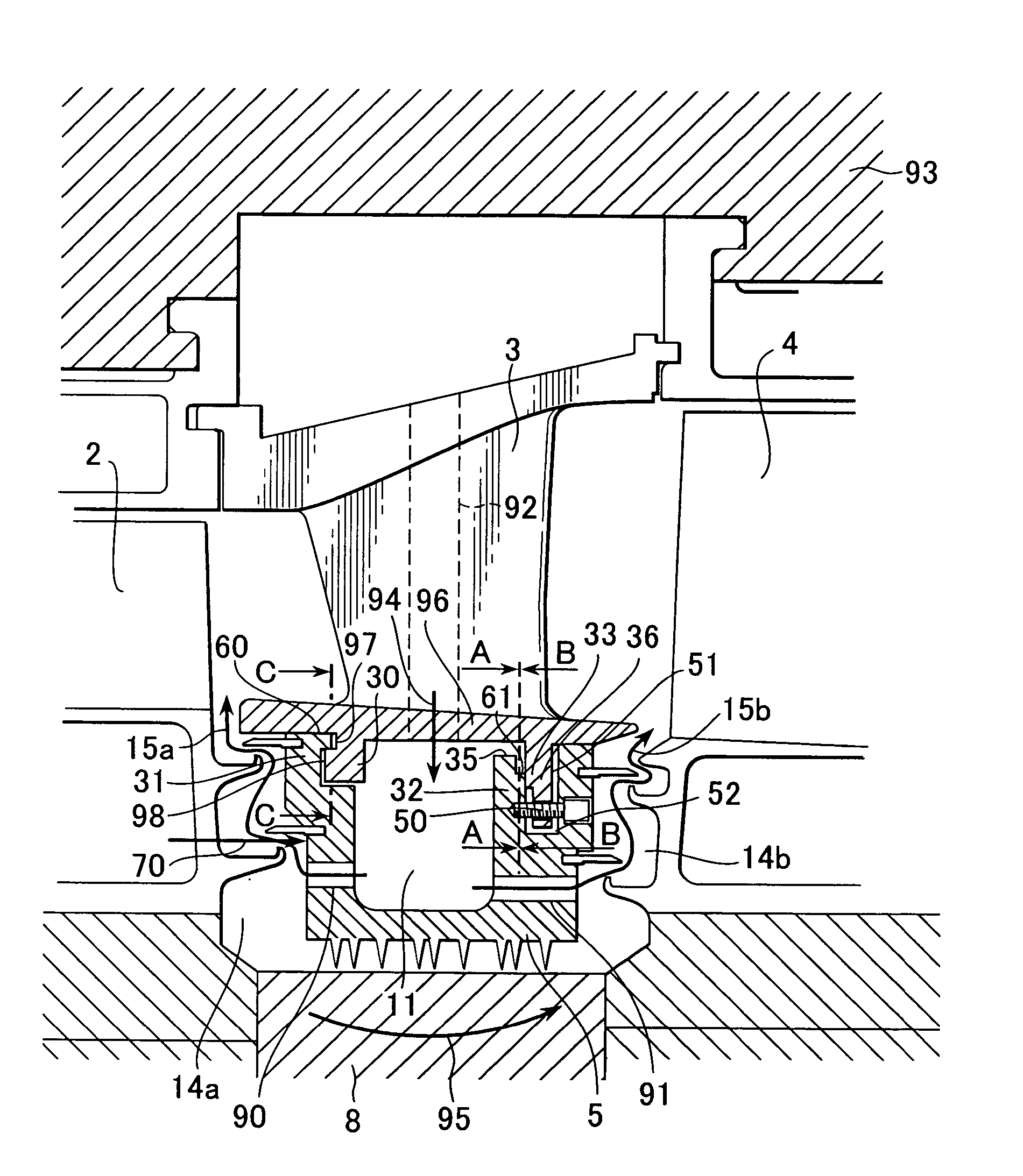
[0022] The structure of the gas turbine will be described with reference to FIG. 2. FIG. 2 shows a section of a principal part (blade stage section) of the gas turbine according to a first embodiment. An arrow 20 in FIG. 2 indicates the direction of flow of combustion gases. Numeral 1 denotes a first stage nozzle vane, 3 denotes a second stage nozzle vane, 2 denotes a first stage rotor blade, and 4 denotes a second stage rotor blade. Also, numeral 5 denotes a diaphragm, 6 denotes a distance piece, 7 denotes a first stage rotor disk, 8 denotes a disk spacer, and 9 denotes a second stage rotor disk.

[0023] The first stage rotor blade 2 is fixed to the rotor disk 7, and the second stage rotor blade 4 is fixed to the rotor disk 9. The distance piece 6, the rotor disk 7, the disk spacer 8, and the rotor disk 9 are integrally fixed by a stub shaft 10 to form a turbine rotor as a rotating member. The turbine rotor is fixed coaxially with not only a rotary shaft of a compressor, but also a ...

second embodiment

[0042]FIG. 6 shows a second embodiment of the present invention. According to this embodiment, in the downstream-side engagement portion between the second stage nozzle vane 3 and the diaphragm 5, a slope 39 is formed in the diaphragm hook 32 on the side closer to the outer periphery from the sealing interface. Further, a slope 40 is formed in the nozzle vane hook 33 on the side closer to the inner periphery from the sealing interface. More specifically, each slope 39, 40 is formed as a hook wall surface inclined at any desired angle from the direction perpendicular to the turbine rotary shaft. Even with such a structure, a sealing interface 61b (indicated by a hatched area in FIG. 6) is formed substantially in a band-like shape, and therefore the amount of the sealing air unintentionally leaking through the downstream-side engagement portion can be reduced. Further, similar advantages can also be obtained with such a modification that a recessed step portion is formed in one of the...


PUM


Abstract

A gas turbine includes a nozzle vane and a sealing unit engaged with the nozzle vane inside a turbine supplied with combustion gases produced by mixing and burning air for combustion and fuel. The nozzle vane and the sealing unit are disposed in a channel of the downward flowing combustion gases on the outlet side of a gas path. A plurality of engagement portions between the sealing unit and the nozzle vane are provided successively from the upstream side toward the downstream side in a direction of flow of the combustion gases, and a downstream one of the plurality of engagement portions has a contact interface formed in a direction across a turbine rotary shaft. A reduction in the thermal efficiency of the gas turbine can be suppressed.

Description

BACKGROUND OF THE INVENTION [0001] 1. Field of the Invention [0002] The present invention relates to a gas turbine and a gas turbine cooling method. [0003] 2. Description of the Related Art [0004] In a gas turbine, air is compressed by a compressor and fuel is added to the compressed air to produce an air-fuel mixture. The air-fuel mixture is burnt and resulting high-temperature, high-pressure combustion gases are used to drive the turbine. Thermal efficiency of an overall gas turbine plant can be increased by combining it with another plant, such as a steam turbine. Meanwhile, in a recent gas turbine, a pressure ratio of the combustion gases has been increased with intent to increase the thermal efficiency by using the gas turbine alone. For that reason, the differential pressure across each turbine blade provided in a gas path in a turbine section has been increased in comparison with that in the past. This gives rise to the necessity of reducing the amount of sealing air leaked t...

Claims


Application Information

Patent Timeline
IPC IPC(8): F01D9/00F01D9/02F01D11/02F02C7/18
CPCF01D5/081F01D11/025F01D11/001
Inventor KIZUKA, NOBUAKIMARUSHIMA, SHINYANODA, MASAMIHIGUCHI, SHINICHIHORIUCHI, YASUHIRO
Owner MITSUBISHI POWER LTD
Learn More