
Switchable and programmable electrode configuration

Inactive Publication Date: 2006-02-09
INT REHABILITATIVE SCI
View PDF44 Cites 16 Cited by
  • Summary
  • Abstract
  • Description
  • Claims
  • Application Information

AI Technical Summary

Problems solved by technology

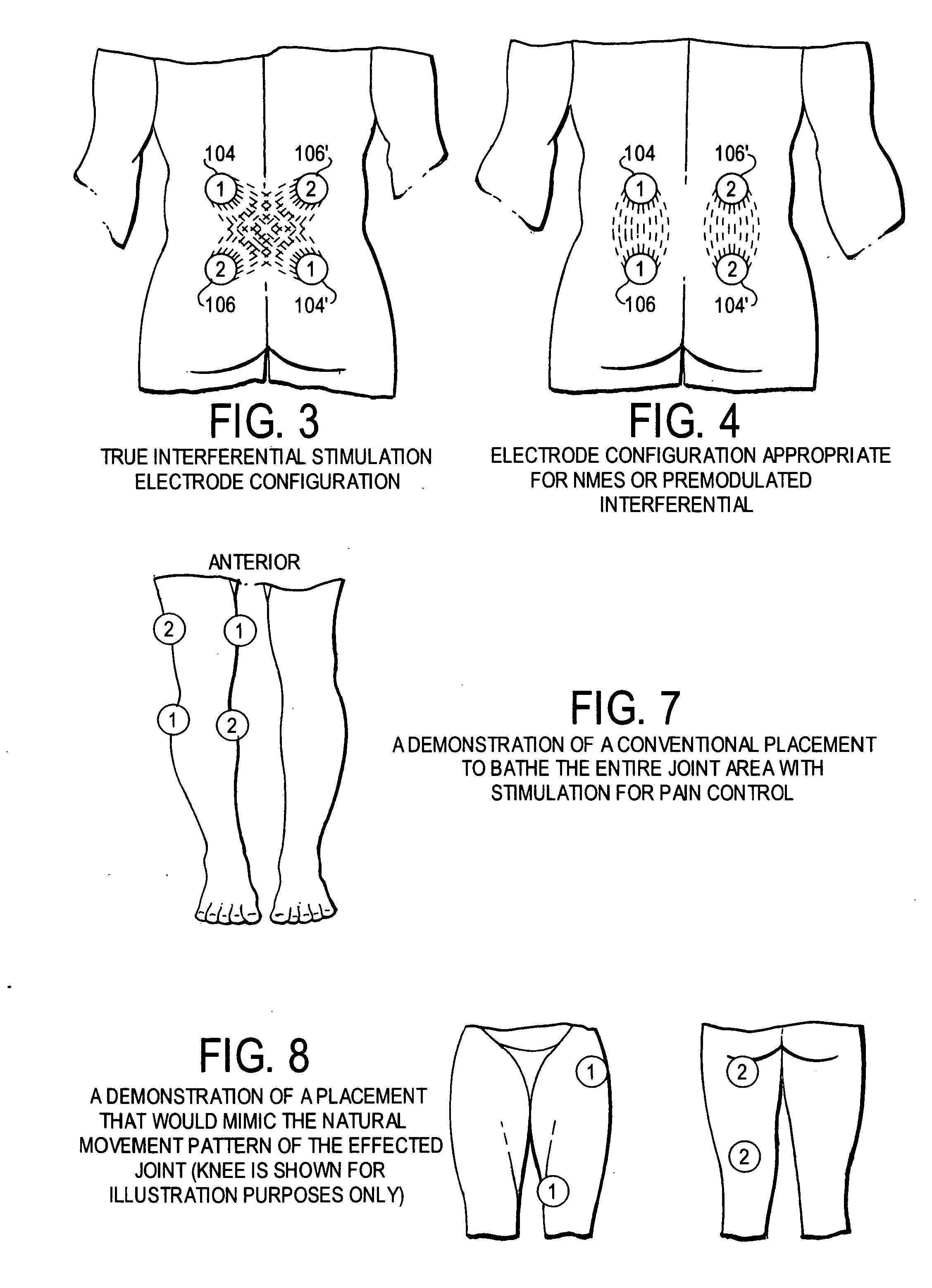
Previously, patients were required to manually change the electrode configuration (but not necessarily the electrode placement) from a cross pattern to a longitudinal pattern, which is inconvenient.

Method used


Image

  • Switchable and programmable electrode configuration
  • Switchable and programmable electrode configuration
  • Switchable and programmable electrode configuration

Examples


Embodiment Construction

[0022] This disclosure provides and discloses exemplary embodiments. In particular, the specification discloses one or more embodiments that incorporate the features of the invention. The embodiment(s) described, and references in the specification to “one embodiment”, “an embodiment”, “an example embodiment”, etc., indicate that the embodiment(s) described may include a particular feature, structure, or characteristic, but every embodiment may not necessarily include the particular feature, structure, or characteristic. Moreover, such phrases are not necessarily referring to the same embodiment. Further, when a particular feature, structure, or characteristic is described in connection with an embodiment, persons skilled in the art may effect such feature, structure, or characteristic in connection with other embodiments whether or not explicitly described.

[0023] Embodiments may be implemented in hardware, firmware, software, or any combination thereof. Embodiments of the inventio...


PUM


Abstract

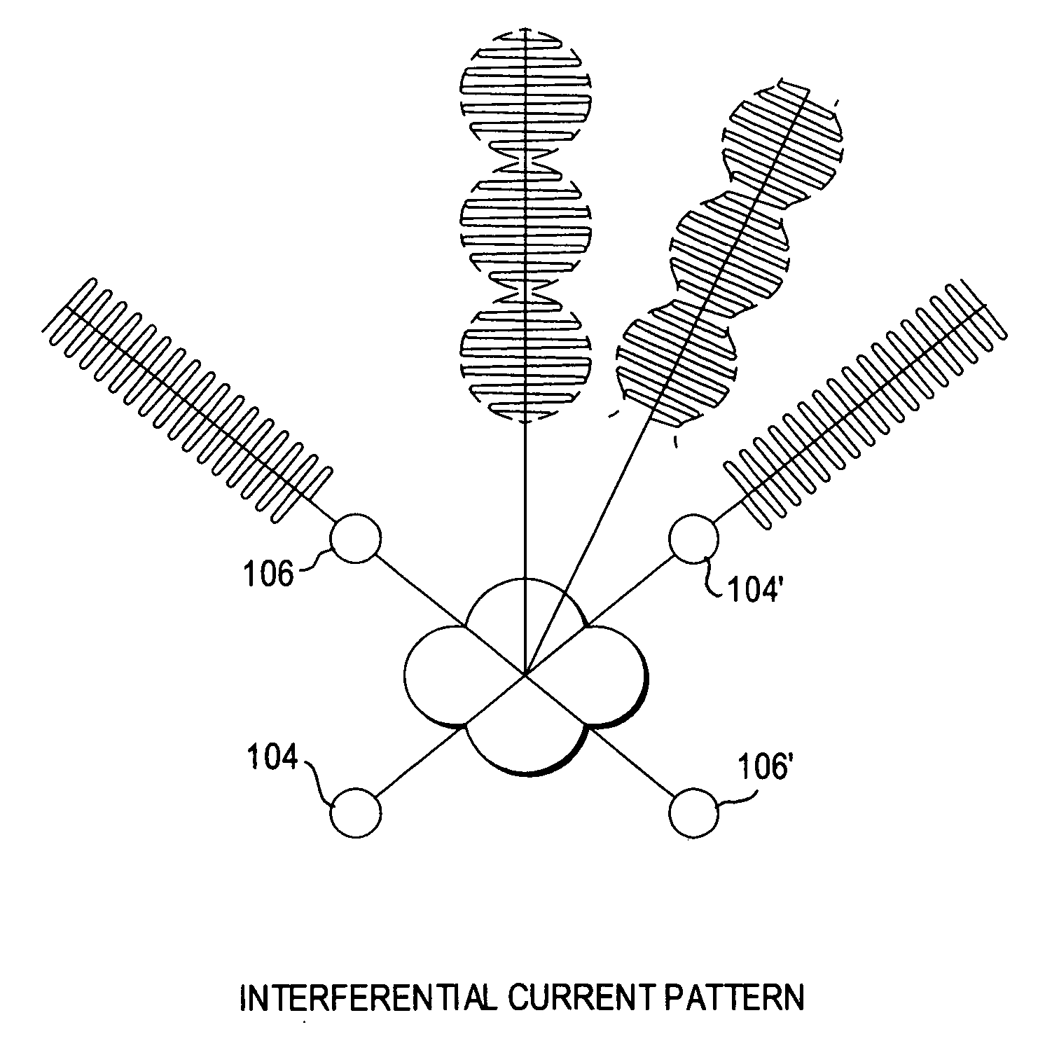
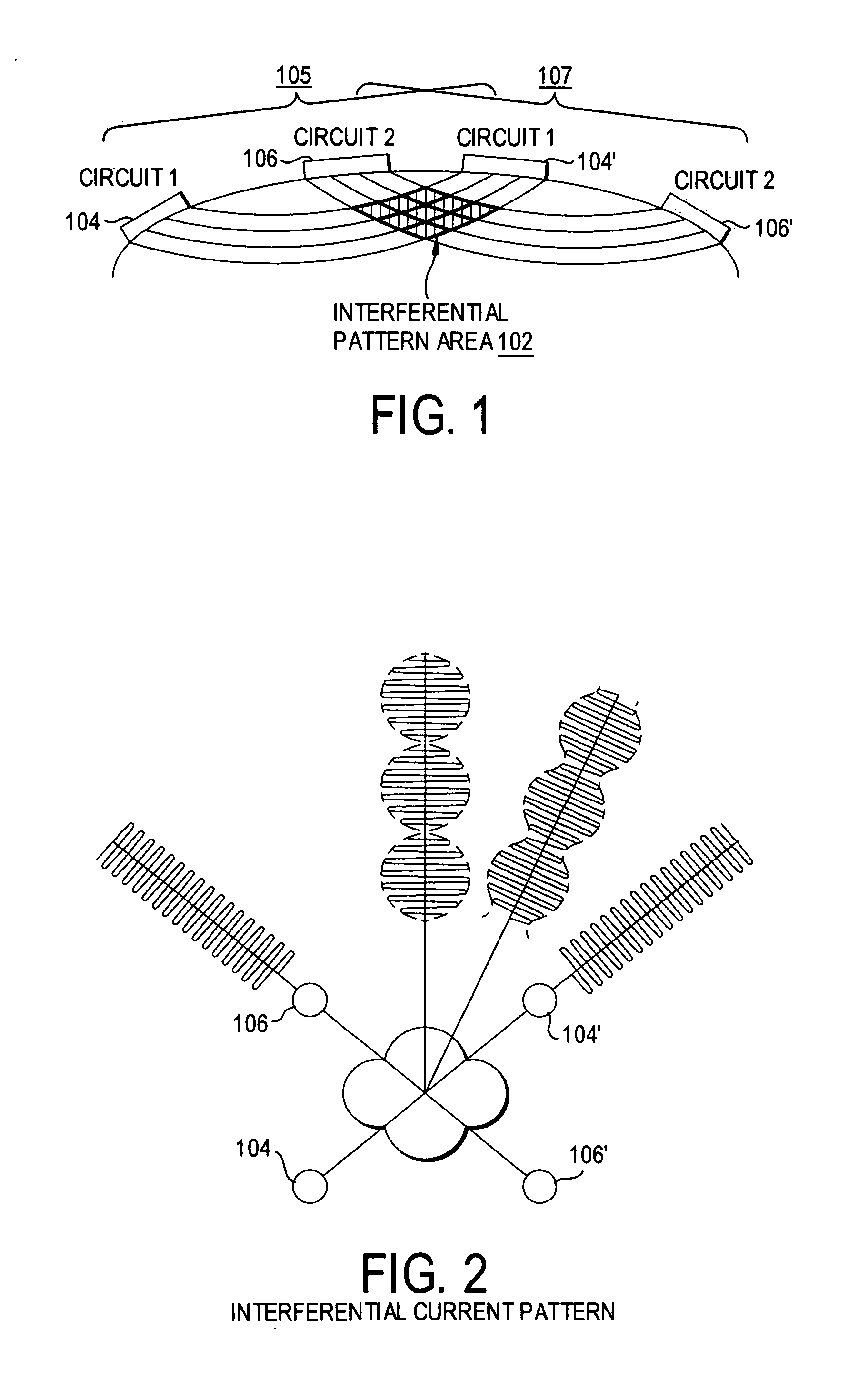
An electrode configuration for surface electrical stimulation to treat chronic and acute pain electrically re-routes current through one of a variety of possible switching means to selectively use a set of electrodes in different modes, for example, in a cross current mode or a longitudinal current mode.

Description

CROSS REFERENCE TO RELATED CASES [0001] This application claims priority of U.S. Provisional Patent Application Ser. No. 60 / 599,012, filed Aug. 6, 2004, the entire specification of which is incorporated herein by reference.FIELD OF THE INVENTION [0002] The present invention is generally related to surface electrical stimulation and, more particularly, is related to a system that uses a switchable and programmable electrode configuration during sequential stimulation BACKGROUND OF THE INVENTION [0003] Surface Electrical Stimulation (also referred to as Transcutaneous Electrical Nerve Stimulation therapy or “TENS” or Neuromuscular Electrical Stimulation, “NMES”) delivers electrical pulses across the skin for various purposes. One of the main indications for Surface Electrical Stimulation (SES) is the relief of acute or chronic pain. Another type of SES (with different parameter sets and electrode configurations) is Neuromuscular Electrical Stimulation (NMES) and is used primarily but ...

Claims


Application Information

Patent Timeline
Patent Type & Authority Applications(United States)
IPC IPC(8): A61N1/18A61N1/32
CPCA61N1/323A61N1/36185A61N1/36021
Inventor CARROLL, WILLIAM J.
Owner INT REHABILITATIVE SCI
Learn More